Low profile ink jet cartridge assembly

a low-profile, ink-jet technology, applied in printing and other directions, can solve the problems of increasing printer cost and ability of consumers, increasing the width and height of ink-jet cartridges, and difficulty in increasing the number of heater resistors and flexible circuit sizes, and achieves the effect of simplifying the alignment of cartridges

Inactive Publication Date: 2006-04-11
FUNAI ELECTRIC CO LTD
View PDF27 Cites 12 Cited by
  • Summary
  • Abstract
  • Description
  • Claims
  • Application Information

AI Technical Summary

Benefits of technology

[0008]Another advantage of the invention is that the ink cartridge may be inserted in a carriage in the printer by a single insertion motion. This motion simplifies alignment of the cartridge in the carriage and also provides a wiping motion for the electrical contacts thereby removing surface contaminants that may be present on the contacts.
is that the ink cartridge may be inserted in a carriage in the printer by a single insertion motion. This motion simplifies alignment of the cartridge in the carriage and also provides a wiping motion for the electrical contacts thereby removing surface contaminants that may be present on the contacts.

Problems solved by technology

Conventional ink cartridge designs make it difficult to increase the number of heater resistors and flexible circuit size without also increasing the width and height of the ink cartridge.
As the size of the ink cartridge increases, so also does the size and footprint of the printer thereby increasing printer cost and ability of consumers to use the printers in a variety of locations.

Method used


Image

  • Low profile ink jet cartridge assembly
  • Low profile ink jet cartridge assembly
  • Low profile ink jet cartridge assembly

Examples


Embodiment Construction

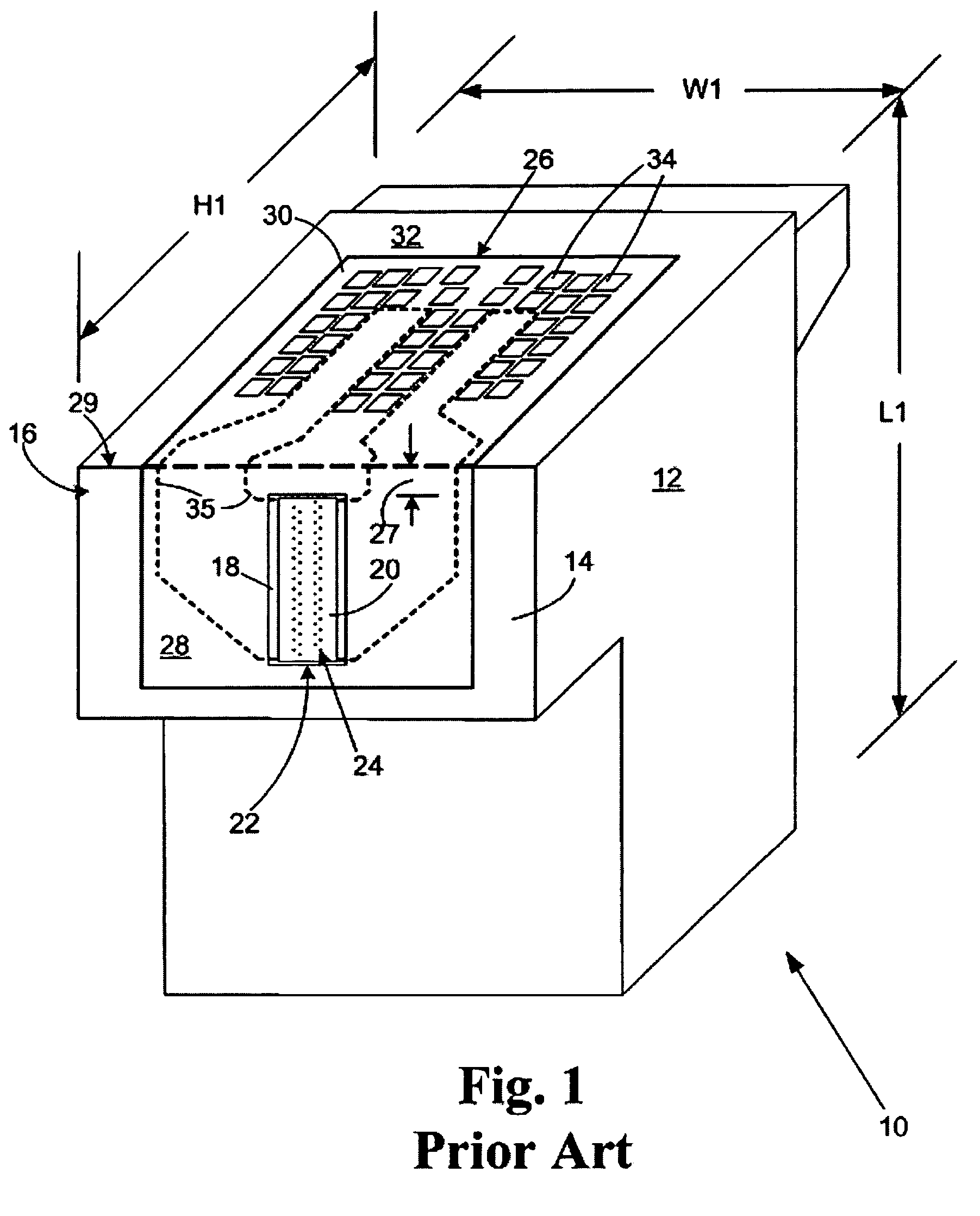
[0020]A conventional ink jet cartridge 10 is shown in perspective view in FIG. 1. The ink cartridge 10 includes a cartridge body 12 having a printhead surface 14 on one end 16 thereof. The printhead surface 14 has attached to it a printhead 18, including a semiconductor substrate 22 and a nozzle plate 20 attached to the semiconductor substrate 22. The semiconductor substrate 22 contains ink ejection devices such as heater resistors or piezoelectric devices that operate to eject ink through nozzle holes 24 in the nozzle plate 20.

[0021]In order to provide electrical impulses to the ink ejection devices on the semiconductor substrate 22, a flexible circuit 26 is attached to the semiconductor substrate 22. The flexible circuit includes a first end 28 attached to the printhead 18 on the printhead surface 14 of the ink cartridge 10 and a second end 30 attached to a side surface 32 of the ink cartridge 10. Contact pads 34 are provided on the second end 30 of the flexible circuit for making...


PUM


Abstract

A low-profile ink jet cartridge assembly for an ink jet printer. The low profile ink jet cartridge assembly includes a substantially rectangular ink jet cartridge body having a printhead side, opposing side surfaces attached to the printhead side and a length, a height, and a width, wherein the length is greater than the height and the width. A printhead containing a semiconductor substrate is attached to the printhead side of the ink cartridge. A flexible circuit having a width, a length, a first edge along the length thereof, a second edge along the length thereof, first printer contact pads along at least a portion of the length thereof adjacent the first edge, and second printer contact pads along at least a portion of the length thereof adjacent the second edge is attached to the ink cartridge on the opposing side surfaces of the cartridge body.

Description

FIELD OF THE INVENTION[0001]The invention relates to improved ink jet printhead assemblies and in particular to printhead assemblies having electrical contacts disposed on opposing side portions of a cartridge body.BACKGROUND[0002]Ink jet technology continues to be improved in order to increase printing speed and print quality or resolution. One means for improving print speed and quality is to increase the number of nozzle holes in an ink jet printhead and to decrease the diameter of the nozzle holes. An increase in the number of nozzle holes also increases a corresponding number of heater resistors on the printhead chip. With an increase in the number of heater resistors, there is also an increase in the number of conductors, circuit connections, and electrical contacts required for operating the printhead. A larger number of circuit connections to a chip often requires a larger chip surface area to make the connections. Accordingly, the number of conductors, circuit connections, ...

Claims


Application Information

Patent Timeline
Patent Type & Authority Patents(United States)
IPC IPC(8): B41J2/14B41J2/175
CPCB41J2/17553B41J2/17526
Inventor GRAF, PAUL WILLIAMFOWLER, JOHN RICHARDROWE, KRISTI MAGGARDHOWARD, TIMOTHY LORNRUSSELL, MATTHEW JOESPIVEY, PAUL TIMOTHYANDERSON, FRANK EDWARD
Owner FUNAI ELECTRIC CO LTD
Why Eureka
Try Eureka