Image-capturing apparatus with asymmetric vibration element

a vibration element and image-capturing technology, applied in the field of image-capturing apparatuses, can solve the problems of increasing manufacturing costs, deteriorating image quality, and increasing the number of parts, and achieve the effect of effective dust removal and simple configuration

Inactive Publication Date: 2015-02-24
SAMSUNG ELECTRONICS CO LTD
View PDF13 Cites 1 Cited by
  • Summary
  • Abstract
  • Description
  • Claims
  • Application Information

AI Technical Summary

Benefits of technology

[0011]The invention provides an image-capturing apparatus capable of effectively removing dust using a simple configuration to prevent a position of a vibration node from being fixed when dust is removed by vibrating a vibration plate.
[0013]In the image-capturing apparatus, the vibration partitioning unit may divide and may deliver the vibration, whereby vibrations due to different modes may be delivered to the vibration plate, vibration nodes may be reduced to a minimum level, and thus a dust removal function may be improved.
[0016]One end of the vibration suppression plate may be connected to the vibration generating unit and the other end of the vibration suppression plate may be connected to the vibration plate. The vibration suppression plate may suppress the vibration of the vibration generating unit and may divide the vibration delivered to the vibration plate.
[0019]When the vibration generated by the vibration generating unit is delivered to the vibration plate, the vibration is divided by the cut part and then is delivered, thereby being possible to generate vibrations due to the different modes in both sides of the vibration plate with respect to the cut part. That is, the vibrations due to the different modes may propagate to a surface of the vibration plate, thereby suppressing vibration nodes to a minimum level, and thus, a dust removal function may be improved.

Problems solved by technology

Dust stuck on an optical device near an image surface of an imaging device may be included in a captured image, and thus, may deteriorate image quality.
However, this increases manufacturing costs due to a more complicated driving circuit.
However, according to Japanese Patent Publication No. 2010-119049, because it is necessary to separately form the two vibration members that operate at different frequencies, device configuration becomes more complicated, the number of parts increases, and the number of manufacturing processes increases resulting in an increase manufacturing costs.
Also, due to the use of two vibration members, it is necessary to arrange a relatively large space in an apparatus, which may make it difficult to reduce the size of the apparatus.
Accordingly, the vibration propagation due to the different modes may intensively occur in both sides of the cut part.

Method used


Image

  • Image-capturing apparatus with asymmetric vibration element
  • Image-capturing apparatus with asymmetric vibration element
  • Image-capturing apparatus with asymmetric vibration element

Examples


Embodiment Construction

[0039]Hereinafter, the invention will be described in detail by explaining exemplary embodiments of the invention with reference to the attached drawings.

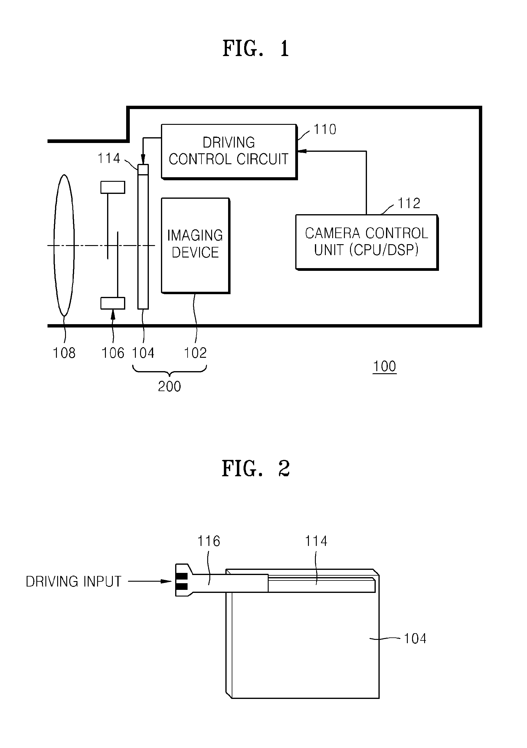
[0040]FIG. 1 is a block diagram illustrating a configuration of an image-capturing apparatus 100, according to an embodiment of the invention.

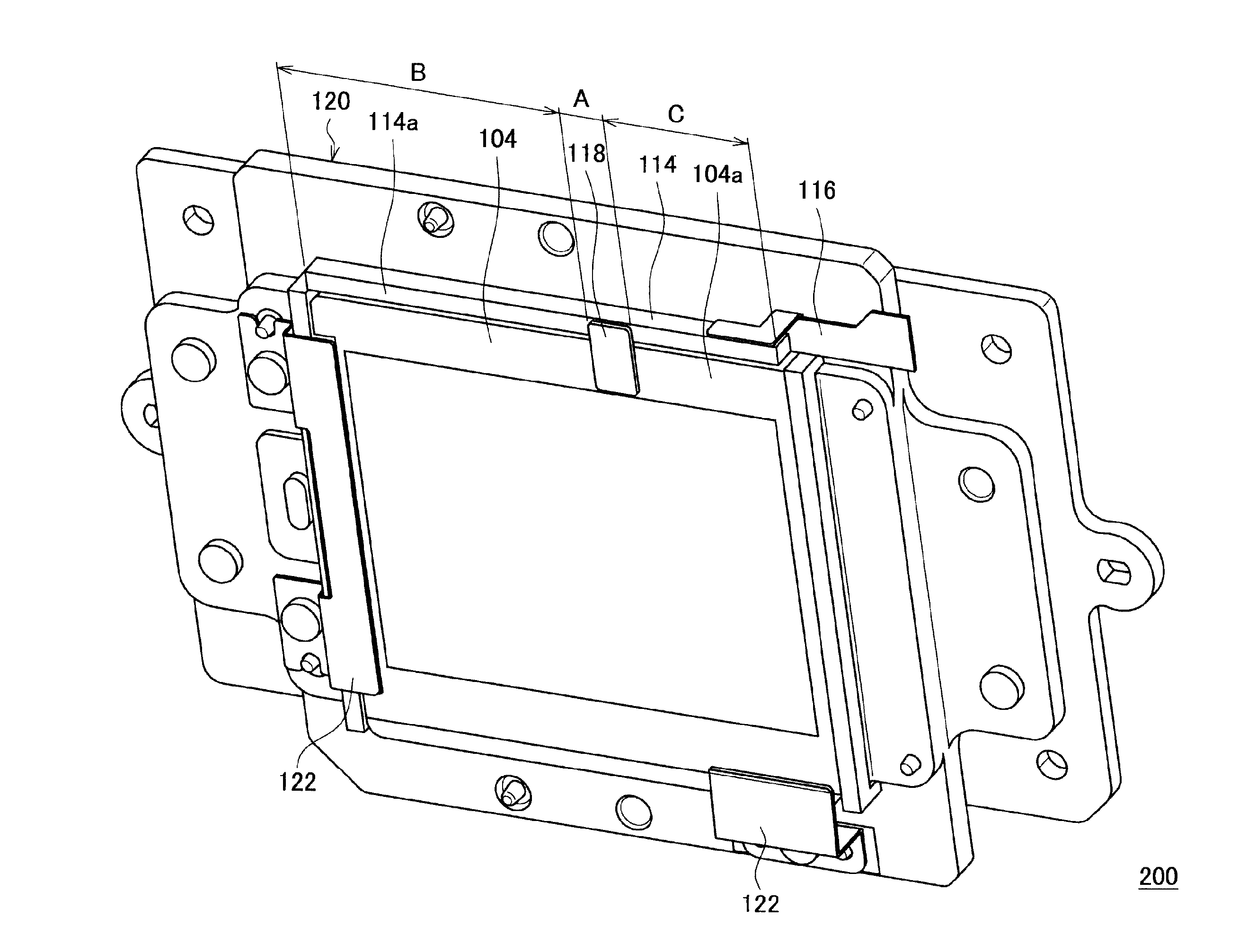
[0041]The image-capturing apparatus 100 includes an imaging device 102, a vibration plate 104, a vibration generating unit 114, and a vibration partitioning unit. Although the vibration partitioning unit is not illustrated in FIG. 1, vibration partitioning units are discussed below in connection with in FIGS. 4, 5, 6A, 6B, 7, 8A, 8B, and 9-12.

[0042]A shutter unit 106 and an imaging optical system 108 may be disposed in front of the imaging device 102. Also, the image-capturing apparatus 100 may include a driving control circuit 110 for controlling driving of the vibration plate 104, and a camera control unit 112 such as a central processing unit (CPU) and / or digital signal processor (DSP).

[00...


PUM


Abstract

An image-capturing apparatus including an imaging device to convert light into an electrical signal; a vibration plate disposed in front of the imaging device to transmit the light to the imaging device; a vibration generating unit mounted on the vibration plate and to generate a vibration when a driving signal is input to the vibration generating unit; and a vibration partitioning unit mounted on at least one of the vibration plate or the vibration generating unit to asymmetrically deliver the generated vibration to the vibration plate.

Description

CROSS-REFERENCE TO RELATED PATENT APPLICATIONS[0001]This application claims the priority benefit of Japanese Patent Application No. 2010-252321, filed on Nov. 10, 2010 in the Japan Patent Office; Japanese Patent Application No. 2010-252317, filed on Nov. 10, 2010 in the Japan Patent Office; and Korean Patent Application No. 10-2011-0056335, filed on Jun. 10, 2011 in the Korean Intellectual Property Office, the disclosures of which are incorporated herein their entireties by reference.BACKGROUND[0002]1. Field of the Invention[0003]The invention relates to an image-capturing apparatus, and more particularly, to an image-capturing apparatus capable of effectively removing dust by vibrating a vibration plate in a plurality of vibration modes.[0004]2. Description of the Related Art[0005]Recently, pixel pitch has been decreasing as the number of pixels implemented by imaging devices has increased. Dust stuck on an optical device near an image surface of an imaging device may be included i...

Claims


Application Information

Patent Timeline
Patent Type & Authority Patents(United States)
IPC IPC(8): H04N5/228H04N5/225G02B27/00H04N5/217
CPCG02B27/0006H04N5/2171H04N23/811H04N23/55
Inventor SHIRONO, MASAHIRO
Owner SAMSUNG ELECTRONICS CO LTD
Why Eureka
Try Eureka