
Multiple-material golf club head with scarf joint

a golf club head and multi-material technology, applied in the field of multi-material golf club heads, can solve the problems of large stress placed on the adhesive, permanent damage to the club, and the structure is not optimized to address the significant stress placed on the bond region and other parts

Active Publication Date: 2017-06-20
TOPGOLF CALLAWAY BRANDS CORP
View PDF52 Cites 22 Cited by
  • Summary
  • Abstract
  • Description
  • Claims
  • Application Information

AI Technical Summary

Benefits of technology

The present invention is a golf club head with a composite crown that is attached to a hollow body using an adhesive. The composite crown has a scarf joint attachment region with a tapered edge. The bond flange has a front region and a back region with different thicknesses. The back region has a second constant thickness. The transition region has a width of at least 0.400 inch. The front region may not have any convex or concave curvature. The bond flange may have a maximum width of no less than 0.100 inch and no more than 0.400 inch. The difference in thickness between the second constant thickness and the first constant thickness may be at least 0.010 inch. The transition region has a width of at least 0.400 inch. The composite material used for the crown may be compression molded. The technical effects of the invention include improved performance and aesthetics.

Problems solved by technology

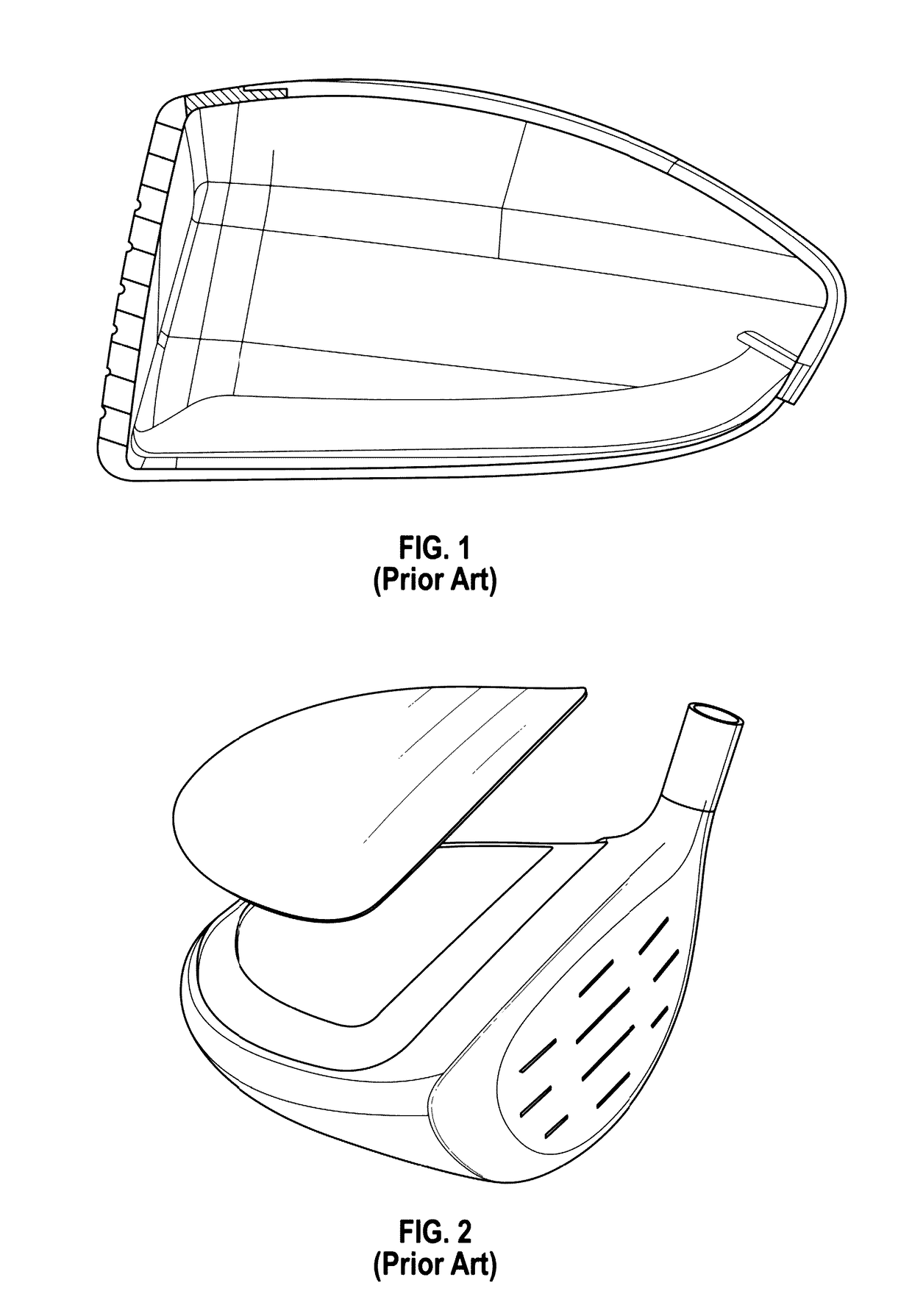
This “step”-type prior art structure, though relatively straightforward to manufacture, is problematic because it creates a high-stress area at the front of the bond joint, which means that a great deal of stress is placed on the adhesive when the golf club head impacts a golf ball.
This causes the crown to separate from the body at the bond region, which becomes visible to a golfer after repeated use and often leads to permanent damage to the club.
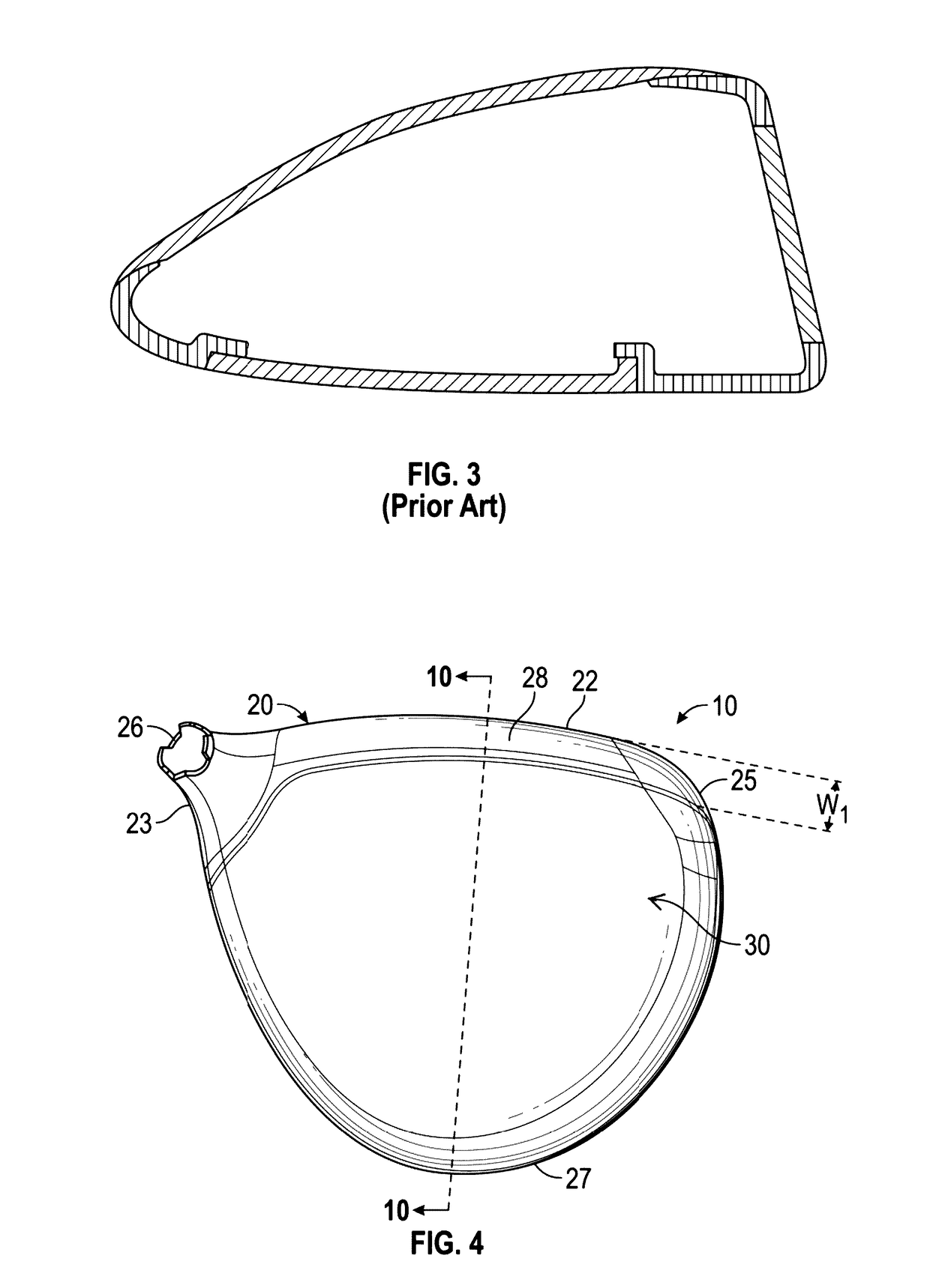
The prior art discloses other types of bond region structures, including a basic scarf joint shown in FIG. 3 (disclosed in U.S. Patent Application Publication Number 2015 / 0045134), but this structure is not optimized to address the significant stresses placed on the bond region and other parts of the golf club head when the head repeatedly impacts golf balls.

Method used


Image

  • Multiple-material golf club head with scarf joint
  • Multiple-material golf club head with scarf joint
  • Multiple-material golf club head with scarf joint

Examples


Embodiment Construction

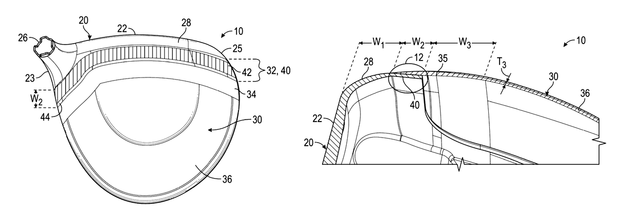
[0028]The present invention introduces a solution to the problems set forth above by providing a crown with an improved scarf joint construction and thickness distribution in combination with a golf club head having improved support flanges.

[0029]A preferred embodiment of the present invention is shown in FIGS. 4-12. In this embodiment, the golf club head 10 comprises a body 20 having a striking face 22, a heel 23, a sole 24, a toe 25, a hosel 26, a rear side 27, a face extension 28 extending rearwards away from the striking face 22, a bond flange 40 extending rearwards away from the face extension 28, an upper opening, and a rear flange 50 extending away from the rear side 27 of the sole 24 towards the striking face 22 at an angle α that is preferably less than 90°. The golf club head 10 also comprises a crown 30 that is permanently bonded to the body 20 with an adhesive to close the upper opening and preferably is composed of a material such as triax composite, SMC, prepreg plies,...


PUM


Abstract

A multiple-material golf club head with an improved scarf joint between the crown and the body is disclosed herein. The golf club preferably is a driver that has a metal body comprising a striking face, a sole, a return portion, a front flange, and a rear flange, and a composite crown having a scarf joint region, a transitional thickness region directly behind the scarf joint region, and a constant thickness region directly behind the transitional thickness region. The thickness distribution along the crown, in combination with the tapered edge of the scarf joint and its intersection with the front flange, greatly reduces the stress placed on critical portions of the club head and improves overall golf club head durability.

Description

CROSS REFERENCES TO RELATED APPLICATIONS[0001]The present application claims priority to U.S. Provisional Patent Application No. 62 / 280,077, filed on Jan. 18, 2016, the disclosure of which is incorporated by reference in its entirety herein.STATEMENT REGARDING FEDERALLY SPONSORED RESEARCH OR DEVELOPMENT[0002]Not ApplicableBACKGROUND OF THE INVENTION[0003]Field of the Invention[0004]The present invention relates to a multiple material golf club head with an improved attachment region between parts of the head. More specifically, the present invention relates to a golf club head with a composite crown having a scarf joint attachment configuration with a face component of the head.[0005]Description of the Related Art[0006]Golf club manufacturers often combine metallic golf club head bodies with composite crowns to reduce the overall head mass and lower the clubs' center of gravity, thus improving the mass properties of such multiple material heads. The region where the crown is affixed...

Claims


Application Information

Patent Timeline
Patent Type & Authority Patents(United States)
IPC IPC(8): A63B53/04
CPCA63B53/0466A63B2053/0408A63B2209/00A63B60/00A63B53/0408
Inventor DAWSON, PATRICKWATSON, WILLIAM C.DEMILLE, BRANDON D.RICE, BRADLEY C.
Owner TOPGOLF CALLAWAY BRANDS CORP
Learn More