
Half-shaft pre-upsetting cooling system

A cooling system and pre-pier technology, applied in the direction of manufacturing tools, forging/pressing/hammer devices, forging/pressing/hammering machinery, etc., can solve the problems of reducing the service life of the mold, high working frequency, uneven cooling of the mold, etc. Achieve the effects of reducing thermal expansion cracking, prolonging service life, and reducing difficulty in demoulding

Inactive Publication Date: 2011-01-26
QINGTE GRP
View PDF5 Cites 3 Cited by
  • Summary
  • Abstract
  • Description
  • Claims
  • Application Information

AI Technical Summary

Problems solved by technology

[0002] When the pre-piercing process is used in the manufacture of automobile half shafts, the cavity of the pre-piercing mold used is small and the working frequency is relatively high. Therefore, after one bar is processed, the mold has no time to cool the second bar and enters the mold, resulting in The thermal expansion of the mold is not conducive to the stripping of the bar. In severe cases, the hydraulic oil may leak or the hydraulic system may be stuck. Therefore, the pre-pier mold needs to be cooled at any time
The traditional cooling method is to use spraying, but this method can easily cause uneven cooling of the mold, and local cooling speed is too fast to cause cracking, which reduces the service life of the mold. At the same time, spraying can easily wash away the mold lubricant, causing Difficult demoulding of the mold

Method used


Image

  • Half-shaft pre-upsetting cooling system
  • Half-shaft pre-upsetting cooling system

Examples


Embodiment Construction

[0009] Below in conjunction with accompanying drawing and specific embodiment the present invention is described in further detail;

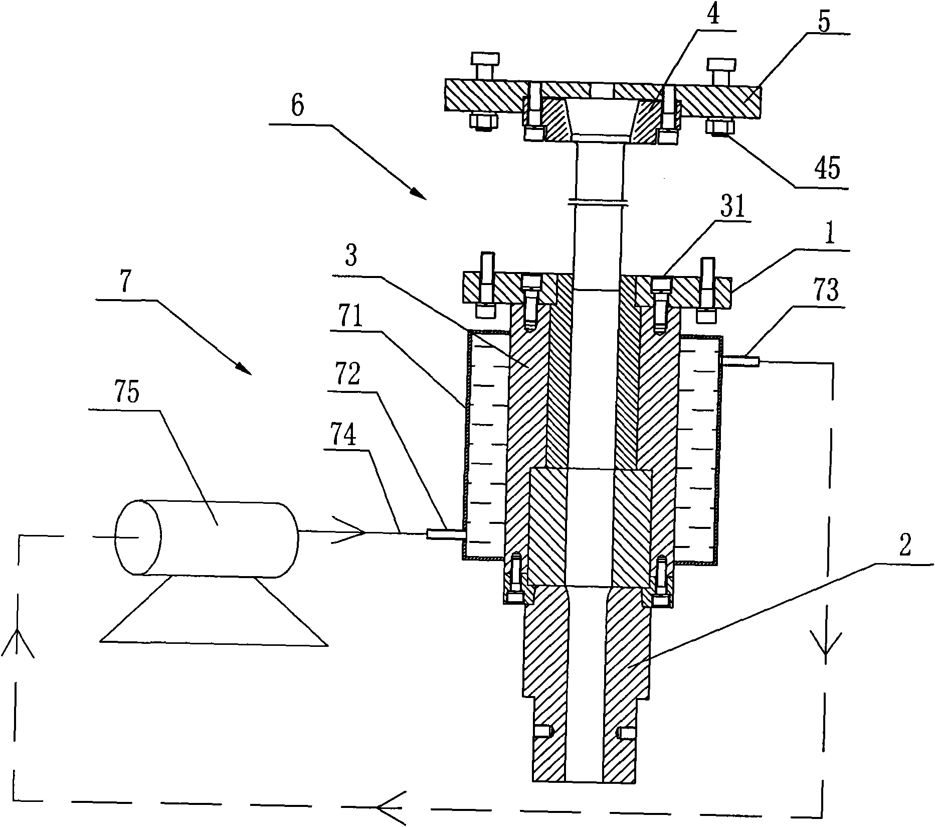
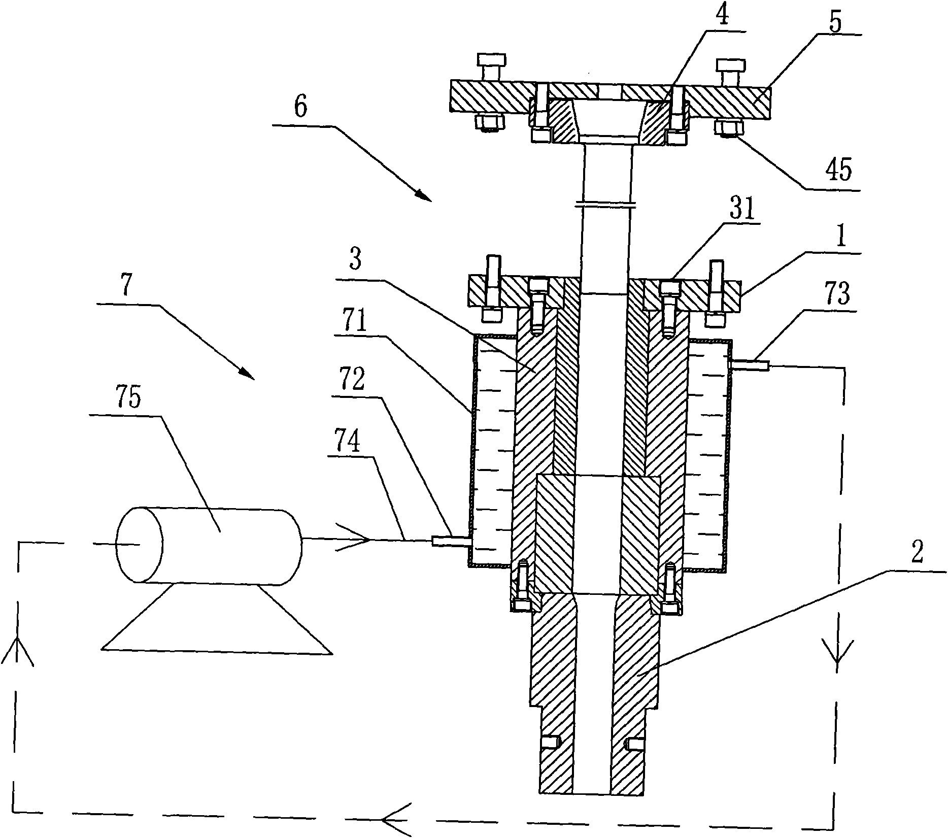
[0010] Such as figure 1 As shown, it is a front view of the semi-axis pre-pier cooling system of the present invention, which includes a pre-pier mold 6 composed of a fixed plate 1, a clamping block 2, a mold protection sleeve 3, an inner insert 4, and an outer insert 5. The fixed plate 1 is connected to the mold protective sleeve 3 through the first screw 31, and the clamping block 2 is arranged in the mold protective sleeve 3, and is embedded with the mold protective sleeve 3 through the fixed plate 1. The inner insert 4, the outer insert The block 5 clamps the pre-pier parts and fixes them with the second screw 45; the mold protective sleeve 3 is provided with a circulating cooling device 7.

[0011] The circulating cooling device 7 includes a circulating water tank 71 arranged outside the mold protective cover 3, and a water inlet 72 and a ...


PUM


Abstract

The invention discloses a half-shaft pre-upsetting cooling system which comprises a pre-mounting mold formed from a fixed disk, a clamping block, a mold protecting sleeve, an inner insert block and an outer insert block, wherein the fixed disk and the mold protecting sleeve are connected through a first screw, and the clamping block is arranged in the mold protecting sleeve and is connected with the mold protecting sleeve through the fixed disk in a scarf joint mode; the inner insert block and the outer insert block tightly clamp pre-upsetting components and parts and are fixed through a second screw; and a circulating cooling device is arranged outside the mold protecting sleeve. The cooling mode of circulating water is adopted, so that he circulating water can take away heat produced during the operation of the mold, and the mold always stays in the temperature state during preheating. Meanwhile, the water flow has low pressure in the mold cooling system so that the self circulation problem can be solved, and a small cooling pump is added so that water can circulate in the mold cooling system; thus, the phenomena of cracking due to heat expansion and difficult demolding are reduced, and the service life of the mold is prolonged.

Description

technical field [0001] The invention relates to the cooling of the pre-piercing process of axle parts of automobiles, in particular to a cooling system for cold pier molds of axle parts such as automobiles and machinery. Background technique [0002] When the pre-piercing process is used in the manufacture of automobile half shafts, the cavity of the pre-piercing mold used is small and the working frequency is relatively high. Therefore, after one bar is processed, the mold has no time to cool the second bar and enters the mold, resulting in The thermal expansion of the mold is not conducive to the stripping of the bar. In severe cases, the hydraulic oil may leak or the hydraulic system may be stuck. Therefore, the pre-pier mold needs to be cooled at any time. The traditional cooling method is to use spraying, but this method can easily cause uneven cooling of the mold, and local cooling speed is too fast to cause cracking, which reduces the service life of the mold. At the ...

Claims


Application Information

Patent Timeline
Patent Type & Authority Applications(China)
IPC IPC(8): B21J1/06B21J13/00
Inventor 纪爱师纪建奕祝欣欣
Owner QINGTE GRP
Learn More