
Method and tool for forming a scarf joint

A technology of molded tools, tapered ends, used in the field of forming beveled joints and tools, which can solve the problems of limited, high autoclave cost, expensive autoclave size, etc., to achieve the effect of reducing cost and cycle time

Inactive Publication Date: 2016-12-07
BLADE DYNAMICS LTD
View PDF2 Cites 4 Cited by
  • Summary
  • Abstract
  • Description
  • Claims
  • Application Information

AI Technical Summary

Problems solved by technology

However, autoclaves are expensive and limited in size
They are especially unsuitable for joints between two elongated members, and the cost of an autoclave long enough to hold these members is prohibitive

Method used


Image

  • Method and tool for forming a scarf joint
  • Method and tool for forming a scarf joint
  • Method and tool for forming a scarf joint

Examples


Embodiment Construction

[0050] The description below refers to the second set of two members as spar cap members, and it is primarily intended that they are spar cap members for use in wind turbine blades. However, the method and tool are equally applicable to any two or more elongate composite members having complementary tapered end surfaces to be joined together.

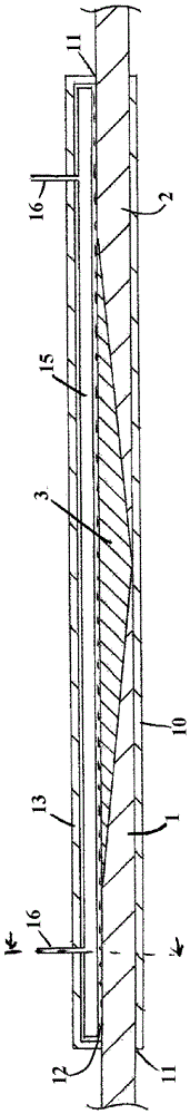
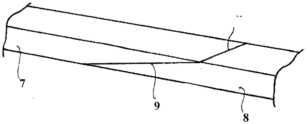
[0051] Figure 1a is a typical example of a double-slope joint formed by the present invention, while Figure 1b A typical example of a single bevel joint.

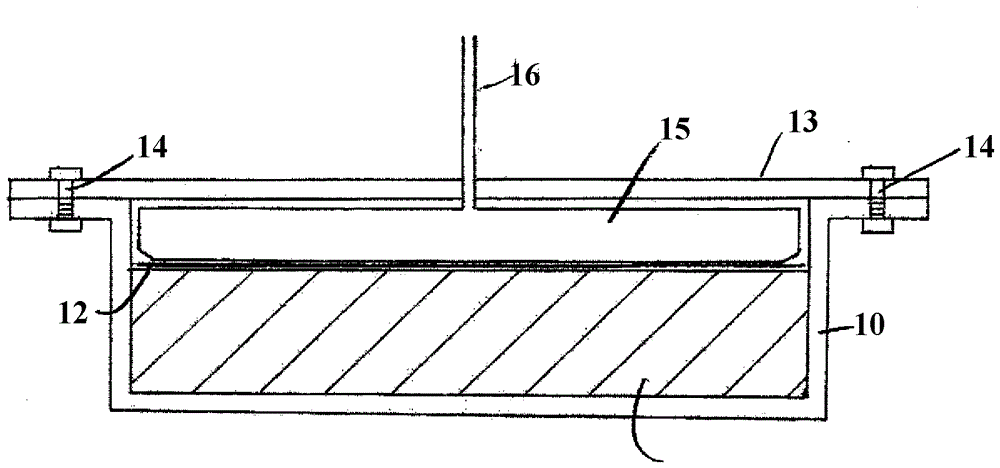
[0052] exist Figure 1a In this case, a first spar cap member 1 is joined to a second spar cap member 2 via a v-connection 3 as described in more detail in WO2012 / 004571. The spar cap members have tapered ends 4, each of which is complementary to the lower face 5 of the connector 3 to which it is bonded, as described below. Each of the members has a composite structure and is made of a plurality of fiber layers impregnated in a resin. Each fiber layer extends progressively in th...


PUM


Abstract

A method of forming a scarf joint between first and second elongate composite components (1,2), each having a complimentary tapered end surface (4,5) is disclosed. At least one of the components is formed of a stack of fibre layers impregnated in resin, with the tapered end surface (4) being formed by each fibre layer extending longitudinally progressively further than the adjacent layer. The method comprises applying adhesive to at least one of the tapered end surfaces (4,5), attaching a moulding tool around the first and second elongate components with their tapered end surfaces being adjacent to one another, applying a positive pressure increase to urge the tapered surfaces (4,5) towards one another without locally reducing the pressure below the vapour pressure of the resin or adhesive throughout the curing process, and curing the resin and adhesive in the moulding tool with the pressure applied.

Description

technical field [0001] The present invention relates to methods and tools for forming a scarf joint between two elongate members. [0002] The invention is particularly useful for forming ramp joints in spar caps of wind turbine blades. However, the concept can be applied more broadly to join any two elongated composite members. Background technique [0003] WO2012 / 004571 describes a method of forming joints in spar caps. By forming such joints, wind turbine blades can be manufactured from multiple small components that are then stacked to form a full length blade. Any such joints must be strong and reliable and should not introduce unwanted parasitic mass into the blade structure. WO2012 / 004571 discloses a method of joining spar caps which allows wind turbine blades to be joined together outside a factory environment so that segments can be transferred in segments and assembled close to their point of use. The disclosure then goes on to describe factory-based assembly m...

Claims


Application Information

Patent Timeline
Patent Type & Authority Applications(China)
IPC IPC(8): B29C70/44B29C70/54B29L31/08
CPCB29C70/44B29C70/54B29L2031/085B29C65/483B29C65/4835B29C65/7802B29C66/1162B29C66/1282B29C66/12841B29C66/14B29C66/342B29C66/5261B29C66/5268B29C66/721B29C66/73751B29C66/73752B29C66/73753B29C66/73754B29C66/73755B29C66/73941B29C66/81455B29C66/9292B29C65/02F03D1/0675Y02E10/72Y02P70/50B29C70/304B29C33/02B29C33/10B29C43/12B29C43/3642B29C65/48B29L2031/08
Inventor P.T.海登P.A.布鲁梅
Owner BLADE DYNAMICS LTD
Learn More