
Mitre joint support

a technology of joint support and mitre, which is applied in the direction of rod connection, furniture parts, manufacturing tools, etc., can solve the problems of rectangular frames, frame that is not ‘square', and unsightly appearan

Active Publication Date: 2021-02-18
TOMM TECH PTY LTD
View PDF0 Cites 3 Cited by
  • Summary
  • Abstract
  • Description
  • Claims
  • Application Information

AI Technical Summary

Benefits of technology

The movement of the moveable portion in this patent allows for easy release of a supported mitre joint, and it can be reversive. In an alternate version, the moveable portion can be moved in either direction to a locked position where it partially embeds within a rail within the supported mitre joint.

Problems solved by technology

Some common problems exist in the creation of rectangular frames.
One problem is the requirement that the rails are connected at precisely 90°.
Errors in cutting, in drilling, or in alignment can result in a frame which is not ‘square’.
In some cases this is merely unsightly.
In other cases, the result may be a final product which does not operate correctly, or fit into a required space.
A second problem is that the mitre joint between rails frequently represents a weak point of the frame.
Where the frame is subject to significant load, or where the frame is used for security purposes, this can represent a difficult problem to address.
Thirdly, a common form of connection of mitre joints between hollow rails requires forcing an internally, preformed 90° bend into the hollow section using an interference fit.
Where there is any misalignment in the rails this method can lead to damage to the rails; looseness of the connection; and / or difficulty in removal of the bend.
Welding can create further problems, such as distortion due to heat and damage to surface coatings.
If a welded joint requires grinding to ensure smoothness, the strength of the join may be compromised.

Method used


Image

  • Mitre joint support
  • Mitre joint support
  • Mitre joint support

Examples


Embodiment Construction

Detailed Description of Preferred Embodiments

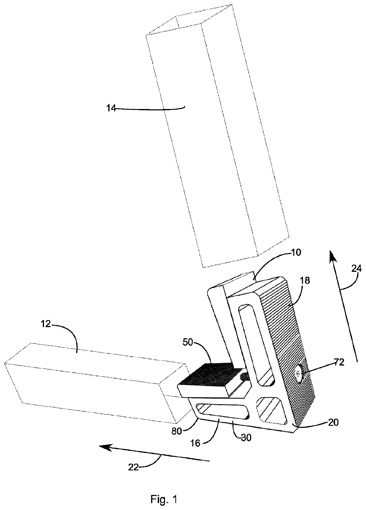
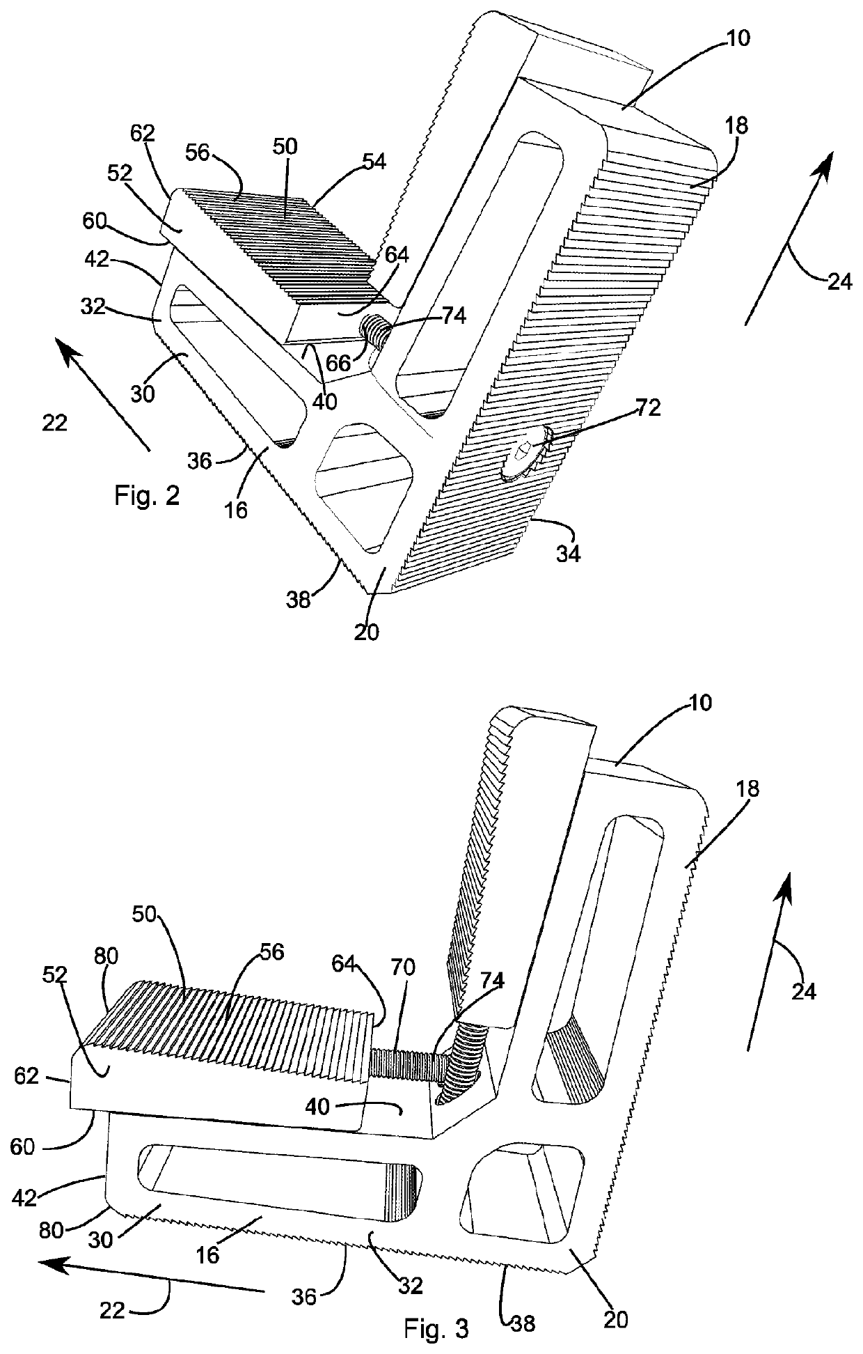
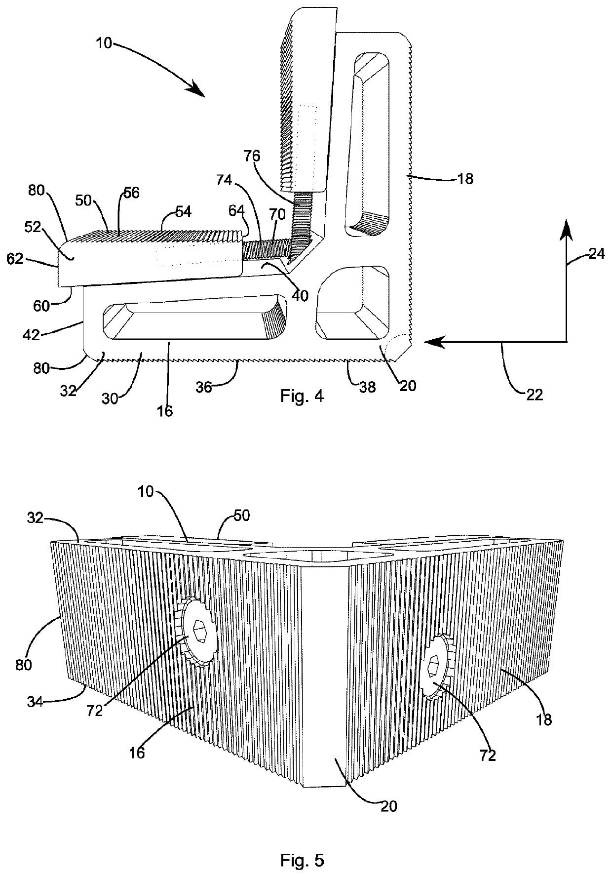
[0045]Referring to the FIGS. 1 to 6, there can be seen a mitre join support 10 which is arranged to connect a first hollow rail 12 to a second hollow rail 14 at an angle of 90°.

[0046]The hollow rails 12, 14 are each square in cross section. It will be appreciated that although the embodiments shown herein are arranged for these particular rails 12, 14 the relative proportions of the mitre join support 10 can be readily altered to accommodate hollow rails of different proportions.

[0047]The mitre join support 10 has a first arm 16 arranged to be inserted within the first hollow rail 12 and a second arm 18 arranged to be inserted within the second hollow rail 14. The first arm 16 and the second arm 18 each extend away from a central region 20.

[0048]The first arm 16 extends away from the central region 20 in a first direction 22. The second arm 18 extends away from the central region 20 in a second direction 24. The first direction 22 is perp...


PUM


Abstract

A support for a mitre joint uses two wedging mechanisms disposed at a characteristic angle. Each wedging mechanism is arranged to locate inside a hollow rail, such as within an extruded hollow beam. The wedging mechanism can be operated from outside the joint in order to clamp the mechanism in position. The mechanism has a self centering capability to assist in accurately locating the rails relative to each other.

Description

[0001]International patent application numbers PCT / AU2017 / 050544 and PCT / AU2018 / 050415, the contents of which are incorporated herein by reference, describe panel systems used primarily for the formation of fences and gates. These systems feature a rectangular frame made of hollow aluminium rails with slats extending between the rails internally of the frame.BACKGROUNDField of the Invention[0002]The present invention relates to the connection of two hollow section beams at an angle to form a mitre joint. The invention has been created in the context of metal fencing panels and gates, but is considered to have wider application, including in the context of metal framed doors and windows.Background to the Invention[0003]The use of aluminium (or other metal) rails to form a rectangular frame is common in the building industry. Such frames may support windows, glass doors, fencing panels, security screens, insect screens and many similar applications.[0004]Some common problems exist in ...

Claims


Application Information

Patent Timeline
IPC IPC(8): B25B5/06F16B7/04B25B5/14
CPCB25B5/068B25B5/147F16B7/0473E06B3/9644E06B3/9648E04F2011/1829A47B2200/00A47B96/14E04H17/1469E04H17/1417E04H17/1448E04H17/1413E06B3/9725E06B3/972
Inventor HODGSON, THOMASHODGSON, RILEY
Owner TOMM TECH PTY LTD
Learn More