Optical apparatus and drive controlling method

a technology of optical equipment and control method, applied in the direction of printers, instruments, camera focusing arrangement, etc., can solve the problems of time lag, the focus lens cannot be followed immediately by the electronic cam,

Active Publication Date: 2017-06-20
CANON KK
View PDF17 Cites 0 Cited by
  • Summary
  • Abstract
  • Description
  • Claims
  • Application Information

AI Technical Summary

Benefits of technology

[0007]The present invention provides an optical apparatus and a control method, which can provide precise autofocus on a moving object in an image-pickup optical system configured to correct a variation of an image plane associated with a magnification variation.

Problems solved by technology

However, due to the performance of the motor for driving the focus lens, the focus lens may not be able to be follow the electronic cam immediately and a time lag occurs until the focus lens follows the electronic cam.

Method used


Image

  • Optical apparatus and drive controlling method
  • Optical apparatus and drive controlling method
  • Optical apparatus and drive controlling method

Examples


first embodiment

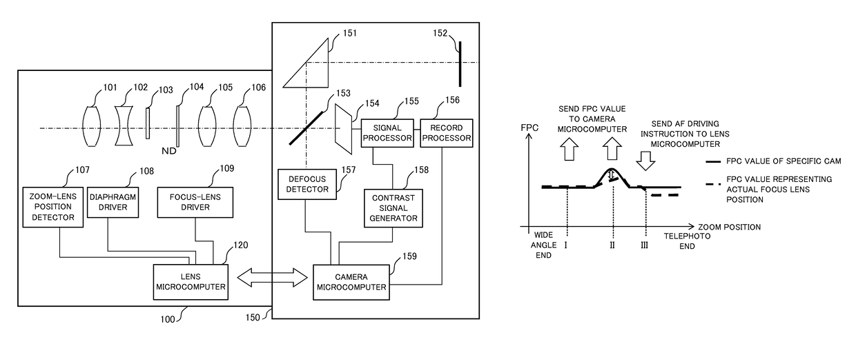
[0057]FIG. 4A is a view illustrating a relationship between the focal length and the position of the focus lens 105 (FPC) in zooming from the wide angle end to the telephoto end when a first drive controlling method of the focus lens 105 is applied. FIG. 4B is a flowchart illustrating principal part of the first drive controlling method of the focus lens 105, and “S” denotes the step. The drive controlling method of the focus lens 105 is implemented and stored in the lens microcomputer 120 as a program that enables a computer to execute the position controlling method. This is true of other embodiment.

[0058]In FIG. 4A, the abscissa axis denotes a focal length (zoom position), and the ordinate axis denotes a position of the focus lens 105 (FPC). A solid line denotes the specific cam similar to that of FIG. 3. A broken line denotes the position (FPC value) of the focus lens 105. A dotted line denotes the position of the focus lens 105 (FPC value) which the lens microcomputer 120 sends...

second embodiment

[0062]FIG. 5A is a view illustrating a relationship between the focal length and the position of the focus lens 105 (FPC) in zooming from the wide angle end to the telephoto end when a second drive controlling method of the focus lens 105 is applied. FIG. 5B is a flowchart illustrating principal part of the second drive controlling method of the focus lens 105, and “S” denotes the step.

[0063]In FIG. 5B, the abscissa axis denotes a focal length (zoom position), and the ordinate axis denotes a position of the focus lens 105 (FPC). A solid line denotes the specific cam similar to that of FIG. 3. A broken line denotes the position of the focus lens 105.

[0064]The lens microcomputer 120 determines whether there is a transmission request for information of the position of the focus lens 105 (S20), waits for the request until it receives it, and sends information on the actual position of the focus lens 105 (S22) if there is (both at the focal lengths I and II). However, this embodiment is ...

third embodiment

[0068]FIG. 6A is a view illustrating a relationship between the focal length and the position of the focus lens 105 (FPC) in zooming from the wide angle end to the telephoto end when a third drive controlling method of the focus lens 105 is applied. FIG. 6B is a flowchart illustrating principal part of the third drive controlling method of the focus lens 105, and “S” denotes the step.

[0069]In FIG. 6B, the abscissa axis denotes a focal length (zoom position), and the ordinate axis denotes a position of the focus lens 105 (FPC). A solid line denotes the specific cam similar to that of FIG. 3. A broken line denotes the position of the focus lens 105.

[0070]The lens microcomputer 120 determines whether there is a transmission request for information of the position of the focus lens 105 (S30), waits for the request until it receives it, and sends information on the actual position of the focus lens 105 if there is (both at the focal lengths I and II) (S32). Next, the lens microcomputer 1...


PUM


Abstract

A controller controls a focus lens driver so as to maintain an in-focus state associated with a magnification variation, based on information on a tracking curve that represents a position of the focus lens corresponding to an object distance and a focal length of an image-pickup optical system. The controller controls the focus lens driver so as to prevent the focus lens from being moved for focusing based on a difference between an actual position of the focus lens and the position of the focus lens indicated by the tracking curve in a case the focus lens driver is driving the focus lens based on information on the tracking curve.

Description

BACKGROUND OF THE INVENTION[0001]Field of the Invention[0002]The present invention relates to an optical apparatus and a drive controlling method, which provide autofocus on a moving object (moving-object AF) using an image-pickup optical system configured to correct a variation of an image plane associated with a magnification variation.[0003]Description of the Related Art[0004]The improved precision of the moving-object AF has recently been increasingly demanded. Japanese Patent Laid-Open No. (“JP”) 2009-128614 proposes a camera configured to acquire a driving target position of a focus lens by using a detected defocus amount for a feedback value to be sent to a controller, to correct the driving target position based on the focus lens potion at the acquisition time, and to control a prediction of a moving object based on the corrected driving target position.[0005]It is known as a tracking control in a rear-focus type magnification varying optical system to correct a variation of...

Claims


Application Information

Patent Timeline
Patent Type & Authority Patents(United States)
IPC IPC(8): H04N5/232G03B13/36G03B3/10
CPCG03B13/36G03B3/10H04N5/23212G03B2205/0046H04N23/672H04N23/673
Inventor UCHIYAMA, MINORU
Owner CANON KK
Why Eureka
Try Eureka