Camera accessory and camera

a technology for accessories and cameras, applied in the field of cameras and camera accessories, can solve problems such as erroneous operation of accessories, and achieve the effect of preventing connection failur

Active Publication Date: 2017-06-20
CANON KK
View PDF72 Cites 29 Cited by
  • Summary
  • Abstract
  • Description
  • Claims
  • Application Information

AI Technical Summary

Benefits of technology

[0009]The present invention provides a camera accessory and a camera, which are capable of preventing connection failure of accessory type determining contacts provided in their mounts.

Problems solved by technology

However, the bayonet mounts of the camera and interchangeable lens disclosed in Japanese Patent Laid-Open No. 09-211645 are not provided with the accessory type determining contacts.
Moreover, the connection failure between the accessory type determining contacts causes the camera to make an erroneous determination of the type of the accessory, which results in setting of an improper communication voltage by the camera for the attached interchangeable lens and thereby may cause an erroneous operation of the accessory.

Method used


Image

  • Camera accessory and camera
  • Camera accessory and camera
  • Camera accessory and camera

Examples


embodiment 1

[Embodiment 1 ]

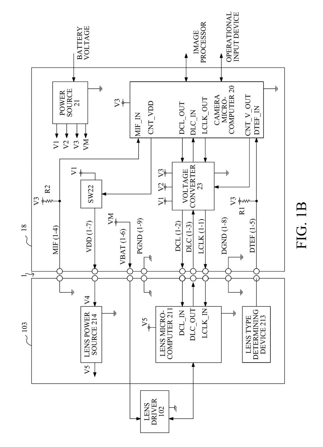
[0031]FIG. 1A shows an interchangeable lens 100 as a camera accessory and a camera 10 to which the interchangeable lens 100 is detachably (that is, interchangeably) attached, which are Embodiment 1 of the present invention and constitute a camera system. The camera 10 and the interchangeable lens 100 each have a mount 1 provided with electrical contacts for supplying source power from the camera 10 to the interchangeable lens 100 and for performing communication therebetween. Although this embodiment describes the interchangeable lens as the camera accessory detachably attachable to the camera, other camera accessories are also included in other embodiments of the present invention.

[0032]The camera 10 includes an image sensor (image pickup element) 11 that photoelectrically converts an object image as an optical image formed by an image taking lens 101 housed in the interchangeable lens 100 and outputs an analog electrical signal. Moreover, the camera 10 includes an A...

embodiment 2

[Embodiment 2]

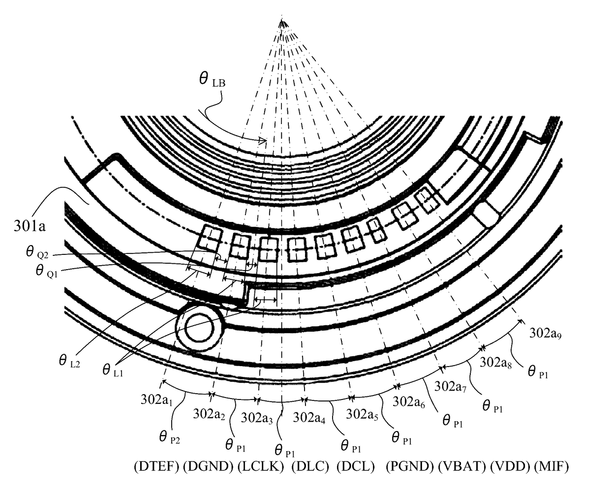
[0144]FIGS. 11A to 11C show, as a second embodiment of the present invention, a case of satisfying the above-described conditions (2) and (3), but not satisfying the conditions (1) and (4). In this embodiment, the pitch P2 and the interval Q2 between the mutually adjacent first and second lens side contact patterns 302ay and 302ay+1 are larger than the pitch P1 and the interval Q1 between the mutually adjacent second lens side contact patterns 302ax and 302ax+1. Moreover, the pitch P2 between the mutually adjacent first and second camera side contact pins 202ay and 202ay+1 is also larger than the pitch P1 between the mutually adjacent second camera side contact pins 202ax and 202ax+1.

[0145]However, the width of the first lens side contact pattern 302ay is equal to L1 that is the width of the second lens side contact pattern 302ax (302ay+1). However, L1 in this embodiment is set to be larger than L1 shown in Embodiment 1, and is set to be larger than the possible pin co...


PUM


Abstract

The camera accessory is attachable to a camera. The camera accessory includes an accessory mount to be detachably coupled with a camera mount). The accessory mount is provided with accessory bayonet claws and brought, by relative rotation with the camera mount, from a first state in which each of the accessory bayonet claws is inserted between camera bayonet claws provided in the camera mount into a second state in which the accessory bayonet claws engage with the camera bayonet claws to complete coupling of the accessory and camera mounts. The camera accessory is further provided with accessory contact surfaces arranged in a relative rotation direction of the mounts in the accessory mount. The accessory contact surfaces includes a first accessory contact surface used for indicating type of the camera accessory and is provided adjacent to the accessory bayonet claw.

Description

BACKGROUND OF THE INVENTION[0001]Field of the Invention[0002]The present invention relates to a camera and a camera accessory interchangeably attachable to the camera such as an interchangeable lens.[0003]Description of the Related Art[0004]Such camera accessories (each hereinafter simply referred to as “an accessory”) receive, in a state of being attached to a camera, supply of power from the camera and perform communication of commands, data or the like with the camera. In order to perform such supply of power and communication, an attachment portion (mount) of the camera and that of the accessory are provided with multiple electrical contacts (each hereinafter simply referred to as “a contact”) in which paired ones are brought into contact with each other to establish electrical connection. Moreover, as a method of the attachment (coupling) of the camera and the accessory, bayonet coupling is often used in which the mounts of the camera and accessory are relatively rotated to cau...

Claims


Application Information

Patent Timeline
Patent Type & Authority Patents(United States)
IPC IPC(8): G03B17/00G03B17/56G03B17/14
CPCG03B17/566G03B17/14G03B17/565
Inventor NISHIO, TETSUYAKONNO, YOSHIHIKOTOKUNAGA, TATSUYUKIHASEGAWA, TAKASHISUGAWARA, AZUSAKIKUCHI, HIROSHI
Owner CANON KK
Why Eureka
Try Eureka