Floor power distribution system

a power distribution system and floor technology, applied in the direction of coupling device details, coupling device connections, arrangement using take-up reel/drum, etc., can solve the problems of system trip hazards, system prone to fluid intrusion, and difficulty in assembling and concealing current floor power distribution systems,

Active Publication Date: 2017-06-20
STEELCASE INC
View PDF268 Cites 22 Cited by
  • Summary
  • Abstract
  • Description
  • Claims
  • Application Information

AI Technical Summary

Problems solved by technology

Current floor power distribution systems are often difficult to assemble and conceal.
Such systems may also be susceptible to fluid intrusion.
Further, these systems may present trip hazards or interfere with the use or positioning of floor equipment.

Method used


Image

  • Floor power distribution system
  • Floor power distribution system
  • Floor power distribution system

Examples


Embodiment Construction

[0051]As required, detailed embodiments of the present disclosure are disclosed herein. However, it is to be understood that the disclosed embodiments are merely exemplary and may be embodied in various and alternative forms. The figures are not necessarily to a detailed design and some schematics may be exaggerated or minimized to show function overview. Therefore, specific structural and functional details disclosed herein are not to be interpreted as limiting, but merely as a representative basis for teaching one skilled in the art to variously employ the teachings of the present disclosure.

[0052]As used herein, the term “and / or,” when used in a list of two or more items, means that any one of the listed items can be employed by itself, or any combination of two or more of the listed items can be employed. For example, if an apparatus is described as containing components A, B, and / or C, the composition can contain A alone; B alone; C alone; A and B in combination; A and C in com...


PUM


Abstract

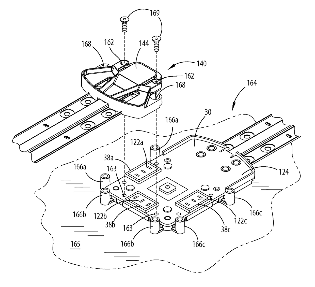
A connection arrangement for a floor power distribution system is provided herein. The connection arrangement comprises a hub arrangement including a hub housing and an electrical connector, the hub housing configured to abut a floor. An adapter is configured to engage the hub housing of the hub arrangement and a seal member is positioned between a downwardly facing surface of the adapter and an upwardly facing surface of the hub housing, wherein a vertical downward force exerted on the adapter compresses the seal member to form a substantially watertight seal between the adapter and the hub housing.

Description

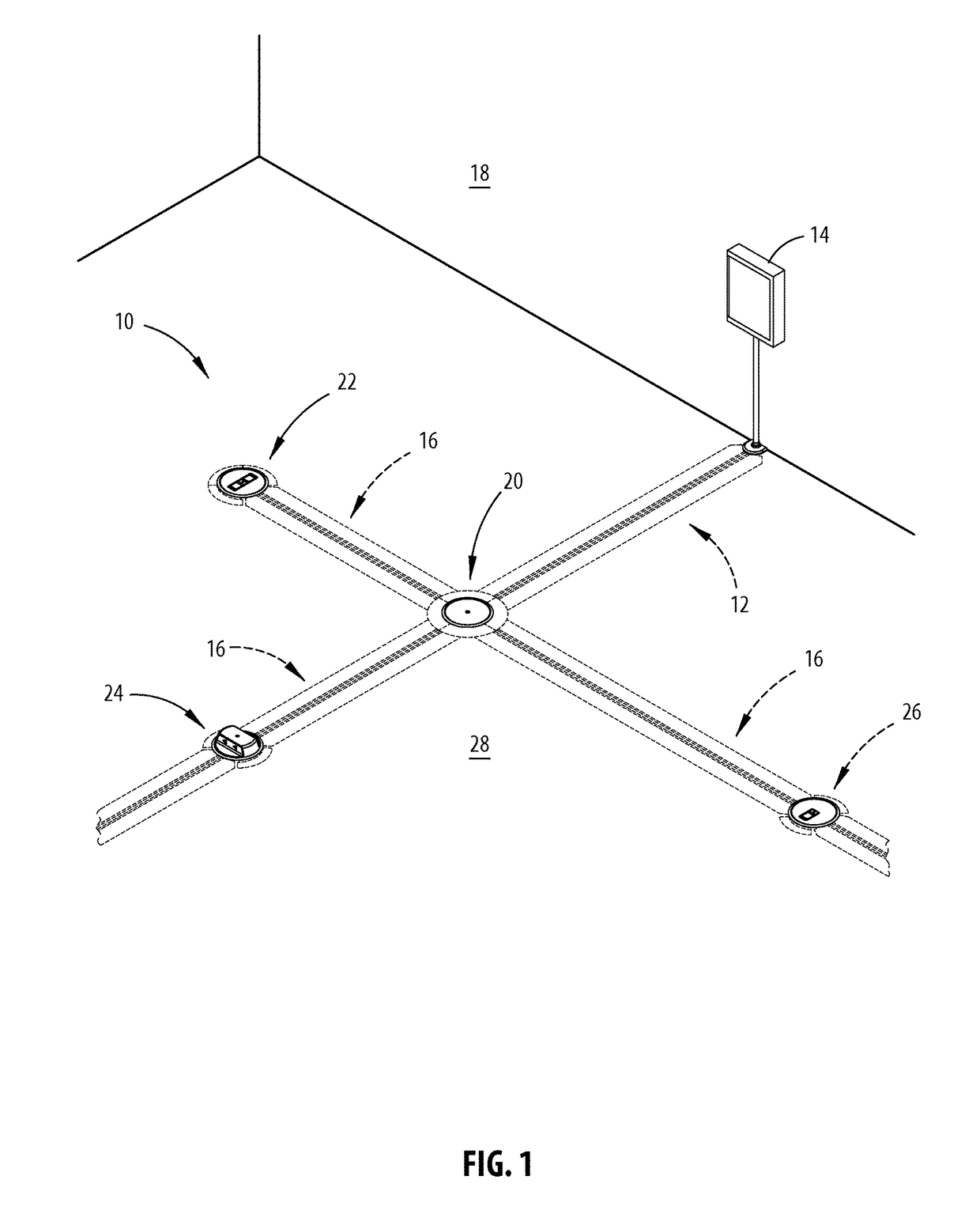
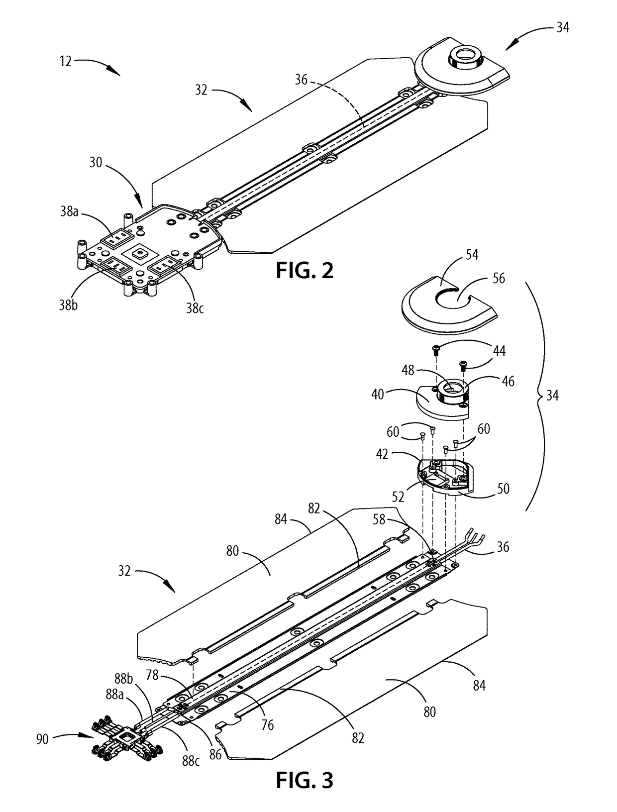
CROSS-REFERENCE TO RELATED APPLICATIONS[0001]This patent application claims benefit to U.S. Provisional Patent Application No. 62 / 049,483, which was filed on Sep. 12, 2014, entitled “FLOOR POWER DISTRIBUTION SYSTEM,” and claims benefit to U.S. Provisional Patent Application No. 62 / 216,051, which was filed Sep. 9, 2015, entitled “FLOOR POWER DISTRIBUTION SYSTEM.” The aforementioned related applications are hereby incorporated by reference in their entirety.BACKGROUND OF THE DISCLOSURE[0002]Current floor power distribution systems are often difficult to assemble and conceal. Such systems may also be susceptible to fluid intrusion. Further, these systems may present trip hazards or interfere with the use or positioning of floor equipment. Thus, there is a need for a floor power distribution system that overcomes these deficiencies.SUMMARY OF THE DISCLOSURE[0003]According to one aspect of the present disclosure, a connection arrangement for a floor power distribution system is provided....

Claims


Application Information

Patent Timeline
Patent Type & Authority Patents(United States)
IPC IPC(8): H01R13/52H02G3/04H02G3/18H02G9/02H02G3/00H01R25/00H02G11/02
CPCH01R13/5221H02G3/0431H02G3/0493H02G3/185H02G9/025H01R13/5219H01R25/006H02G3/00H02G11/02H01R13/5202H02G3/14H01R13/72H01R13/447H02G3/0437
Inventor JONES, DAVID K.PAYNE, JAMIEHOLSTEGE, CODY JAYSCHNEIDER, MARK ANDREW
Owner STEELCASE INC
Why Eureka
Try Eureka