
Apparatus and method for impressing a corrugation into a pipe

a technology of corrugation and pipe, which is applied in the direction of vibration measurement, measurement devices, instruments, etc., can solve the problems of affecting the quality of flexible metal pipes

Active Publication Date: 2017-06-27
NEXANS
View PDF8 Cites 0 Cited by
  • Summary
  • Abstract
  • Description
  • Claims
  • Application Information

AI Technical Summary

Benefits of technology

[0008]The invention is based on the object of improving the apparatus and the method for impressing the corrugation into a pipe such that a consistently uniform rotation can be ensured without said mechanical vibration, which has a negative impact, of the corrugating device.
[0015]By way of the vibration meter and the display apparatus coupled thereto, the operator of the apparatus is automatically notified when disruptive vibrations impair the rotation of the corrugator head. Conclusions can be drawn, for example from a frequency spectrum of measured values which the vibration meter supplies, as to the nature and the origin of the undesired vibrations. For example, vibrations caused by the unbalance of the corrugator head can be distinguished easily from vibrations caused by worn hollow shaft bearings. As a result, it is possible for the operator to counteract excessive vibrations in a targeted manner by readjusting for example the balancing weights on the corrugator head in order to remedy any unbalance. Since the wear to the hollow shaft bearings can be detected early from its vibration characteristics by vibration analysis, the operator can furthermore expediently replace the hollow shaft bearings with new ones when the apparatus is not currently in operation. As a result, an interruption to ongoing production can be avoided and so no unusable lengths of the corrugated pipe arise. In particular, the service life or useful life of the hollow shaft bearings and the bearings of the corrugator head can advantageously be optimized or extended since the bearings are not only protected by the avoidance of vibrations but also only have to be replaced when necessary.

Problems solved by technology

These vibrations can result in considerable damage to the hollow shaft bearings or to bearings of the corrugator head.
Similarly, worn hollow shaft bearings contribute to a worsening in the rotary movement of the hollow shaft and thus of the corrugator head, and this can be manifested by a worsening in the quality of the flexible metal pipe.

Method used


Image

  • Apparatus and method for impressing a corrugation into a pipe
  • Apparatus and method for impressing a corrugation into a pipe
  • Apparatus and method for impressing a corrugation into a pipe

Examples


Embodiment Construction

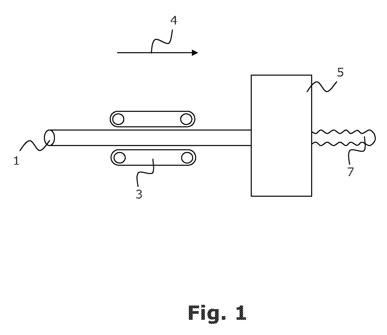
[0019]By means of the arrangement illustrated schematically in FIG. 1, a corrugation is impressed into a smooth metallic pipe 1. The pipe can be manufactured in accordance with a known method, as described for example in EP 1 084 774 B1 mentioned at the beginning. The pipe can consist for example of steel, copper or aluminum.

[0020]In the exemplary embodiment illustrated, the smooth pipe 1 is pushed by means of a take-off apparatus 3 in the direction of the arrow 4 through an apparatus 5 according to the invention, in which the smooth pipe 1 is provided with an annularly or spirally configured corrugation. The corrugated pipe 7 can then be wound onto a reel (not illustrated).

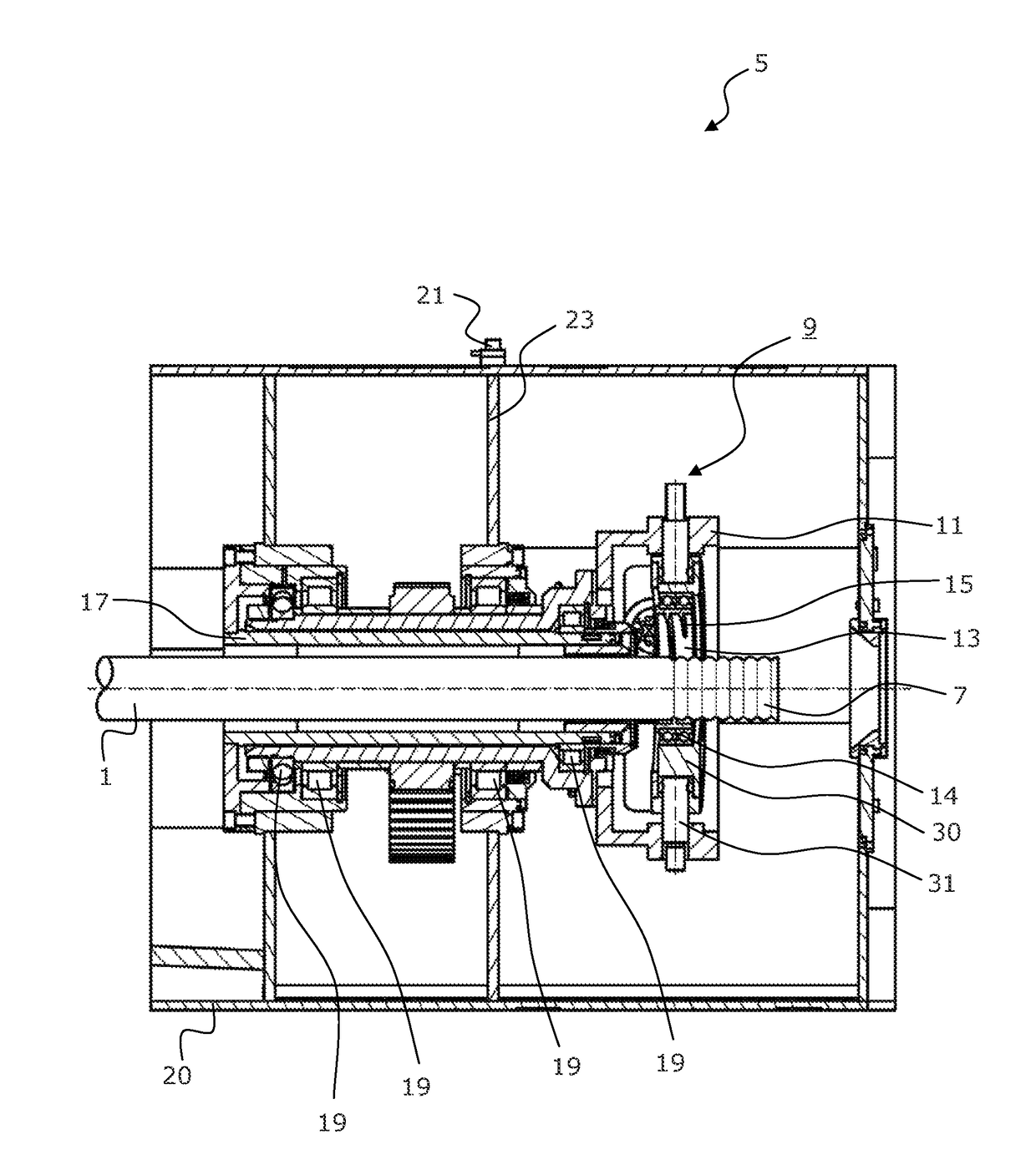
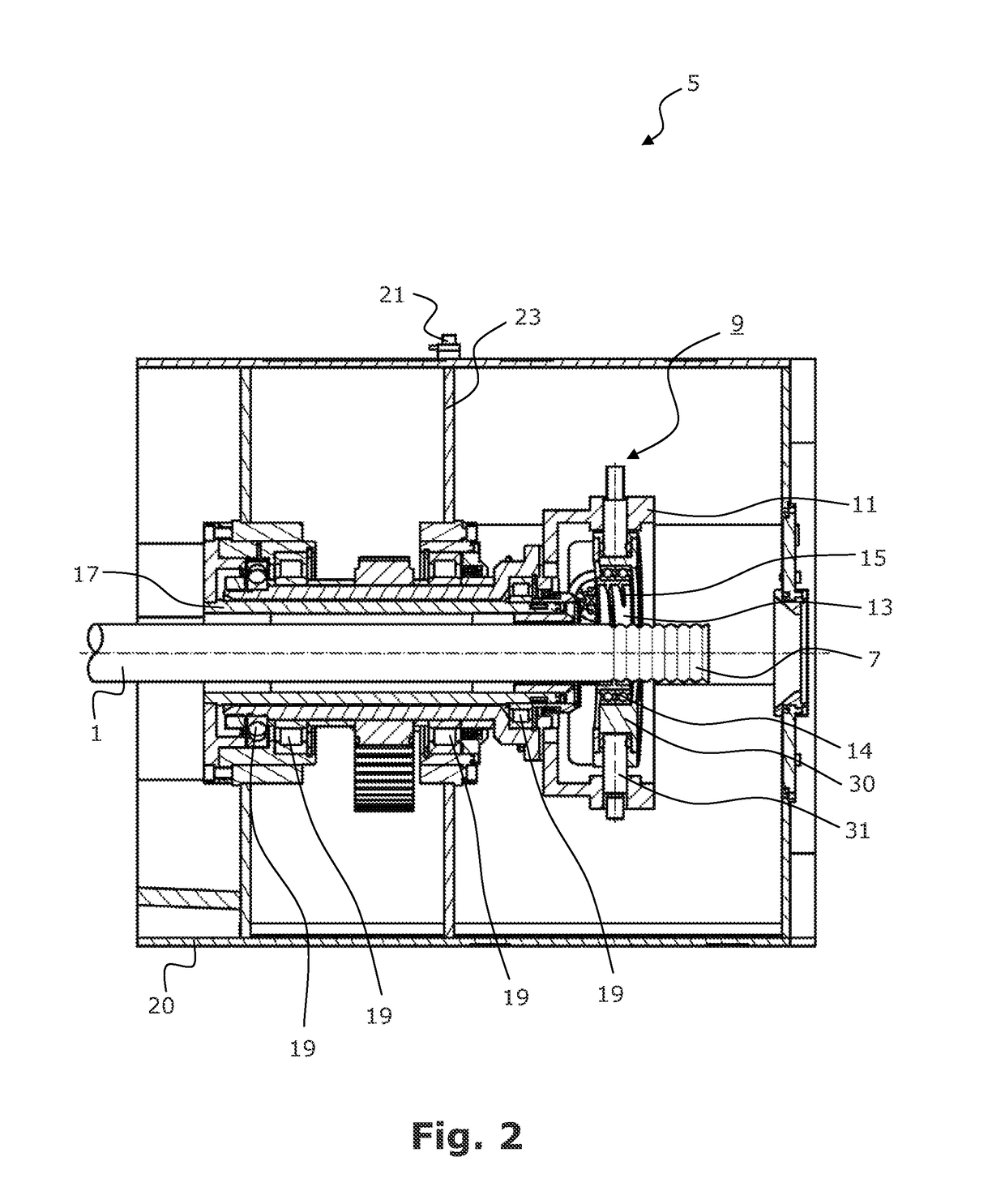
[0021]In FIG. 2, the apparatus 5 according to the invention is illustrated in more detail. It comprises a corrugating device 9 that is known in principle. The corrugating device 9 consists of a corrugator head 11 and a corrugator disk 13. The corrugator head 11 is embodied as an annular disk in the central openin...


PUM

PropertyMeasurementUnit
flexibleaaaaaaaaaa
frequencyaaaaaaaaaa
rotationaaaaaaaaaa

Abstract

An apparatus has a corrugating device through which a pipe is moved producing corrugation in the circumferential direction of the pipe by rotation. The corrugating device has a corrugator head which is rotatable about its axis, and a hollow shaft on which the corrugator head is firmly fitted and via which the corrugator head is driveable in rotation. A vibration measuring means is connected mechanically to the corrugating device for automatically detecting mechanical vibrations of the rotating corrugating device. The vibration measuring means simultaneously detects measured values for vibrations of the hollow shaft which are characteristic of the state of the hollow shaft bearings and measured values for vibrations of the corrugator head which are characteristic of the balancing thereof. A display apparatus displays the measured values detected thereby and / or evaluation results based on the measured values is furthermore provided.

Description

RELATED APPLICATION[0001]This application claims the benefit of priority from European Patent Application No. 13 175 025.9, filed on Jul. 4, 2013, the entirety of which is incorporated by reference.BACKGROUND[0002]Field of the Invention[0003]The invention relates to an apparatus for impressing a corrugation into a metallic smooth pipe, said apparatus having a corrugating device which is driveable in rotation, through which the pipe is moved in its longitudinal direction and which produces the corrugation in the circumferential direction of the pipe by rotation, wherein the corrugating device has a corrugator head which is rotatable about its axis, and a hollow shaft on which the corrugator head is firmly fitted and via which the corrugator head is driveable in rotation, and also to a method for producing the corrugation.[0004]Description of Related Art[0005]An apparatus for manufacturing corrugated pipes is described for example in EP 1 084 774 B1. It is used for manufacturing metal...

Claims


Application Information

Patent Timeline
Patent Type & Authority Patents(United States)
IPC IPC(8): B21D15/06G01H1/00B21D15/04
CPCB21D15/06B21D15/04G01H1/003G01M1/22G01M13/045
Inventor ZUMMACH, VOLKERKRAUSE, THOMASSCHMIDT, ANATOLIHARMS, ADRIAN
Owner NEXANS
Learn More