Vehicle bumper assembly

a technology for bumpers and components, applied in the direction of bumpers, vehicle components, signalling/lighting devices, etc., can solve the problems of attachment elements of the type, far from satisfactory, etc., and achieve the effect of simple and inexpensive solutions

Active Publication Date: 2017-06-27
FCA ITAL
View PDF8 Cites 10 Cited by
  • Summary
  • Abstract
  • Description
  • Claims
  • Application Information

AI Technical Summary

Benefits of technology

[0006]The aim of the present invention is to provide a vehicle bumper assembly that will enable a simple and inexpensive solution to the problem set forth above.

Problems solved by technology

This solution is widely used, but is far from satisfactory, in so far as it has been noted that the attachment elements of the type just described normally break during impact, in particular during types of impact that are tested in the test conditions set down by the European standard ECE R-42, in the case where the fog-lights are located in the area affected by the impact at low speed.

Method used


Image

  • Vehicle bumper assembly
  • Vehicle bumper assembly
  • Vehicle bumper assembly

Examples


Embodiment Construction

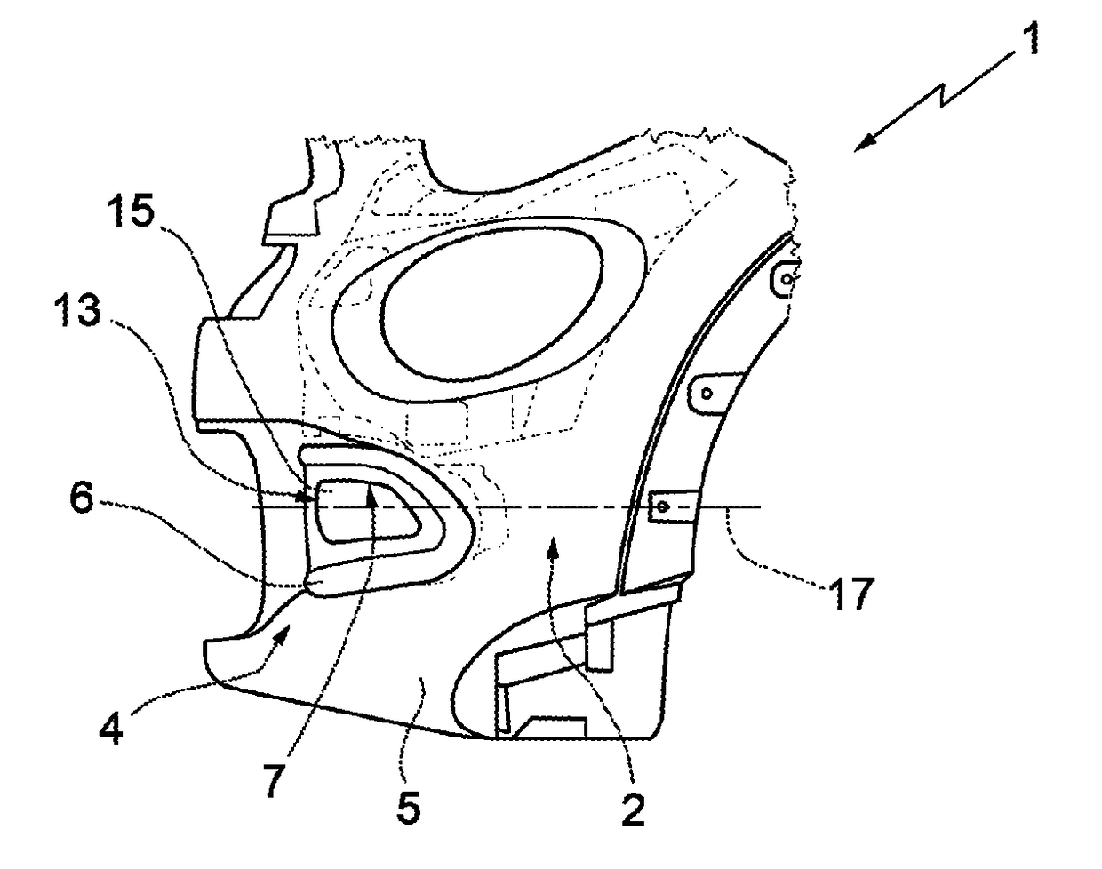
[0012]In FIG. 1, the reference number 1 designates, as a whole, a vehicle (partially represented), which comprises a bumper assembly 2. In particular, the bumper assembly 2 is set at the front end of the vehicle 1, but according to a variant not illustrated the present invention applies also to a rear bumper assembly.

[0013]The bumper assembly 2 has an inner surface 3 (FIGS. 2 and 3) and an outer surface 4, which defines part of the outer shape of the vehicle 1.

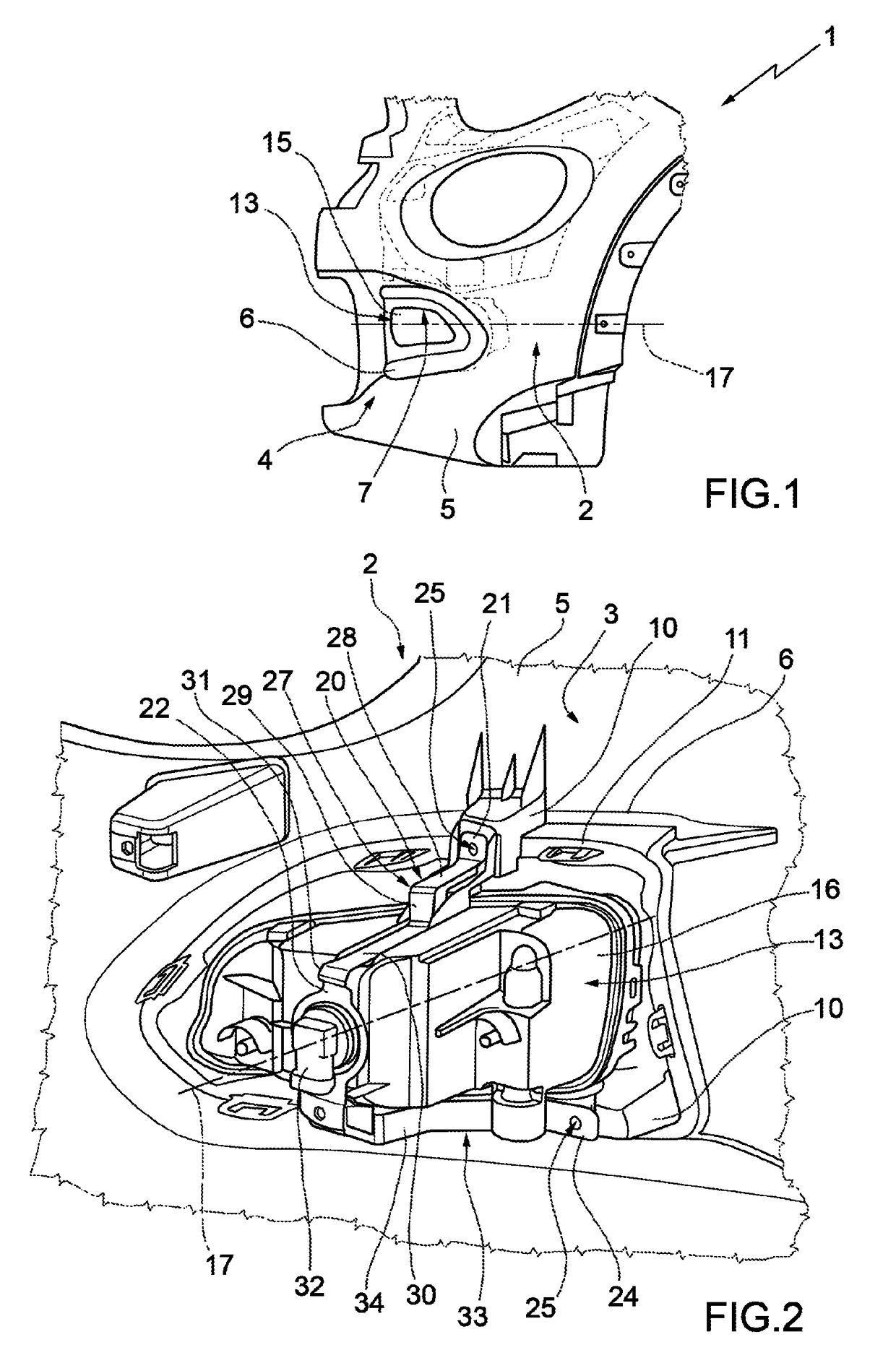
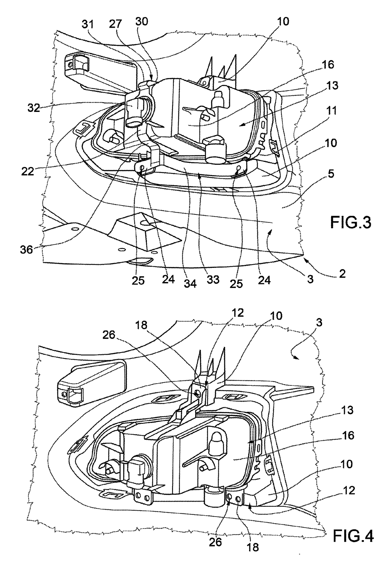
[0014]The bumper assembly 2 comprises a bumper 5, which includes one or more intermediate portions 6 that are provided with respective openings 7. Preferably, as may be seen in FIGS. 2 and 3, on the side of the surface 3 the portions 6 are shaped in such a way as to comprise respective projections 10. In particular, the projections 10 are arranged along the annular edge 11 of each opening 7 and define respective plane resting surfaces 12 (FIG. 4) provided with holes (not visible).

[0015]The bumper assembly 2 comprises, for each...


PUM


Abstract

A vehicle bumper assembly having an outer surface and is a bumper having an opening and a lighting optical assembly engaging the opening is provided. The lighting optical assembly has a front wall, defining part of the outer surface, and a rear shell, which supports the front wall and comprises at least one connecting portion fixed to the bumper. The bumper assembly has an additional coupling element, which has an end fixed to the bumper and a supporting portion set behind the rear shell and is set astride of the rear shell. The material, shape, and dimensions of the additional coupling element are such as to render it elastically deformable in the event of impact at a relatively low speed.

Description

CROSS-REFERENCE TO RELATED APPLICATIONS[0001]This application claims priority under 35 U.S.C. 119(a) to Italian Application TO2014A000928 filed 7 Nov. 2014, the subject matter of which is expressly incorporated herein by reference in its entirety.[0002]The present invention relates to a vehicle bumper assembly.BACKGROUND OF THE INVENTION[0003]As is known, with a front or rear impact at a relatively low speed against other vehicles or else against fixed obstacles, the bumper has the purpose of absorbing energy by undergoing deformation to prevent damage to other components.[0004]In many solutions, the bumper supports optical lighting assemblies; for example, it supports a pair of fog-lights, which are provided with tabs or similar attachment elements, which are made of plastic material, rest on an inner surface of the bumper, and are fixed to the latter, for example via screws or pins.[0005]This solution is widely used, but is far from satisfactory, in so far as it has been noted tha...

Claims


Application Information

Patent Timeline
Patent Type & Authority Patents(United States)
IPC IPC(8): B60R19/48B60R19/50B60R19/18B60Q1/04B60Q1/20B60R19/02
CPCB60R19/50B60Q1/0491B60Q1/20B60R19/18B60R19/023B60R2019/1886B60R2019/505
Inventor CEPOLLARO, FULVIO
Owner FCA ITAL
Why Eureka
Try Eureka