Hinged saw table, system, and method for forming and cutting an elongate workpiece

a technology of elongated workpieces and saw tables, applied in the field of hinged saw tables, can solve the problems of changing the cutting plane angle, affecting the use of workpieces, and affecting the use of workpieces, and achieve the effects of safe use and efficient storage of the hinged saw table, simple and inexpensive solution, and durable construction

Inactive Publication Date: 2005-07-12
MCKEE MELVIN L
View PDF11 Cites 2 Cited by
  • Summary
  • Abstract
  • Description
  • Claims
  • Application Information

AI Technical Summary

Benefits of technology

[0009]The present invention provides a durably constructed hinged saw table with a moveable carrier upon which a portable table saw may be mounted. The operator can then longitudinally position the saw and angle the saw blade to perform a variety of saw operations including square or miter cuts. The hinged saw table may be secured to a work site machine or workshop machine such as, for example, a seamless gutter rollformer. The hinged saw table is secured in a down (or work) position when being used, and may be pivoted on a hinge mechanism to an up (or stored) position. A hinged mast allows the hinged saw table to rest in an inverted storage position on top of the work site machine or workshop machine. This arrangement provides a simple and inexpensive solution to the problem of safely using and efficiently storing the hinged saw table and saw.

Problems solved by technology

A serious problem occurs when a work piece unexpectedly falls or shifts.
The workpiece can become twisted, changing the angle of the cutting plane and rendering the workpiece unusable.
Even worse, an uncontrolled or unstable workpiece can endanger the operator.
These existing solutions are unsafe at worst and at best awkward and cumbersome.
Additionally, many of the existing solutions do not lend themselves to easy storage.

Method used


Image

  • Hinged saw table, system, and method for forming and cutting an elongate workpiece
  • Hinged saw table, system, and method for forming and cutting an elongate workpiece
  • Hinged saw table, system, and method for forming and cutting an elongate workpiece

Examples


Embodiment Construction

[0020]Preferred embodiments of the invention will now be described with reference to various examples of how the invention can best be made and used. Like reference numerals are used throughout the description and several views of the drawing to indicate like or corresponding parts.

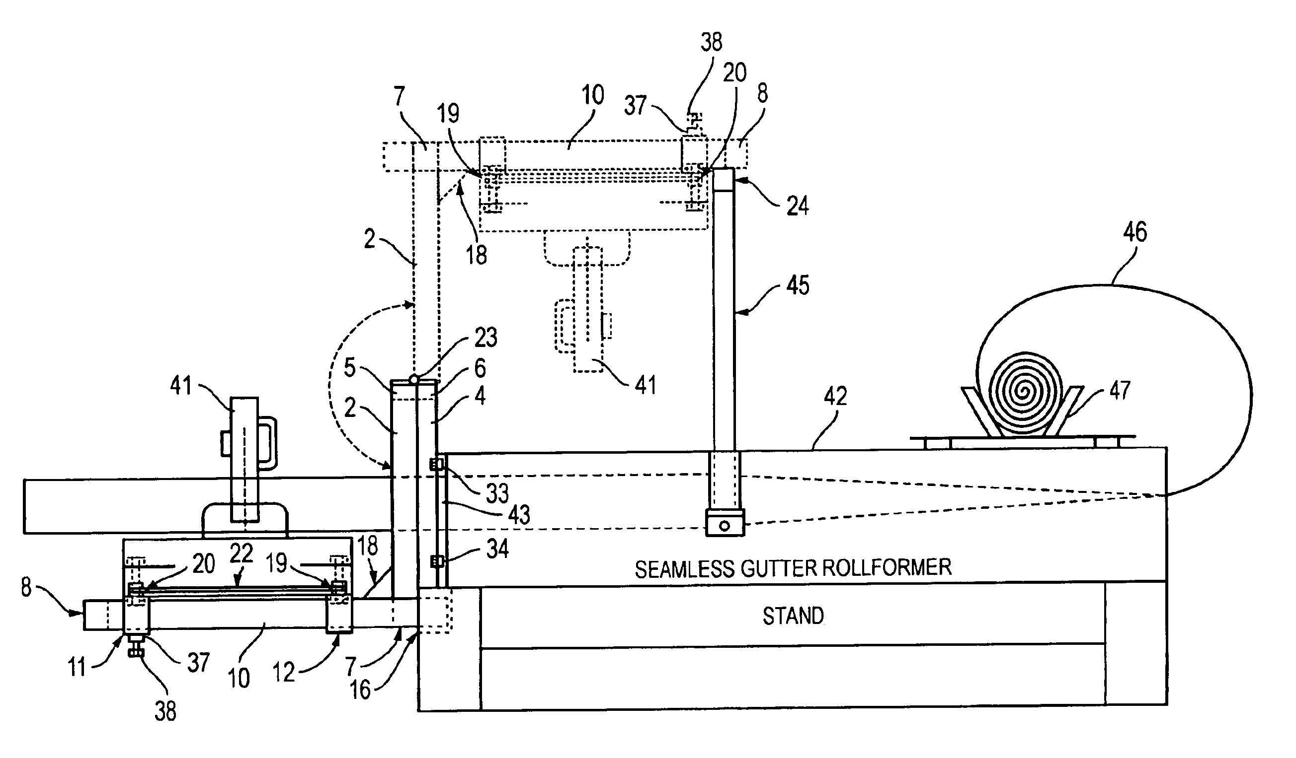
[0021]The present invention provides a hinged saw table, system and method. While the hinged saw table of the present invention may be useful in conjunction with many machines, tools and devices found on a work site, the hinged saw table of the present invention is particularly useful when affixed to a seamless gutter rollformer 42. Again, the hinged saw table may be used in conjunction with any other machine or device where the hinged saw table could be employed, and is particularly useful when used to cut elongate stock that must be cut to a precise length. In the exemplary description herein, the attached machine is referred to as a seamless gutter rollformer.

[0022]Referring now to the drawings, and mo...


PUM

PropertyMeasurementUnit
angleaaaaaaaaaa
heightaaaaaaaaaa
angleaaaaaaaaaa

Abstract

A hinged saw table having a sliding carrier for mounting and sliding a portable table saw. The hinged saw table is mounted adjacent to a forming machine that forms stock that is cut with the portable table saw. Elongate stock exits from an exit aperture in the forming machine, and is directed over the table of the portable table saw mounted upon the movable carrier. The portable table saw may be positioned at the correct point for cutting the stock at a desired length. Square or mitered cuts may be made. For storage purposes, the sliding carrier and table saw may be rotated upward approximately 180 degrees over the top of the forming machine where the carrier and saw rest upside down on a stand. The forming machine may be, for example, a seamless gutter rollformer machine that forms sections of rain gutters for houses or other buildings.

Description

PRIORITY STATEMENT UNDER 35 U.S.C. § 119(E) & 37 C.F.R. § 1.78[0001]This nonprovisional application claims priority based upon the prior U.S. provisional patent application entitled, “Hinged Saw Table,” application No. 60 / 316,919, filed Aug. 29, 2001, in the name of Melvin L. McKee.BACKGROUND OF THE INVENTION[0002]1. Technical Field of the Invention[0003]This invention relates to construction equipment and, more particularly, to a hinged saw table that includes a sliding carrier upon which a portable table saw may be mounted, and a hinge mechanism that enables the hinged saw table to be vertically rotated for storage on top of any machine to which it may be attached.[0004]2. Description of Related Art[0005]In saw operations executed on stock or a workpiece, the stock must be held in place to safely perform the saw operation. A serious problem occurs when a work piece unexpectedly falls or shifts. The workpiece can become twisted, changing the angle of the cutting plane and rendering...

Claims


Application Information

Patent Timeline
Patent Type & Authority Patents(United States)
IPC IPC(8): B23D47/02B23D47/00
CPCB23D47/02Y10T83/7697Y10T83/04Y10T83/7726
Inventor MCKEE, MELVIN L.
Owner MCKEE MELVIN L
Why Eureka
Try Eureka