Main rotor arrangement of an uav-helicopter

a technology of rotors and helicopters, applied in the direction of rotors, vessel construction, other chemical processes, etc., can solve the problem of not being able to control the deflection in any other way, and achieve the effect of controlling the deflection of the hub

Inactive Publication Date: 2012-07-19
SAAB AB
View PDF9 Cites 2 Cited by
  • Summary
  • Abstract
  • Description
  • Claims
  • Application Information

AI Technical Summary

Benefits of technology

[0006]Since the main rotor arrangement comprises a damping assembly for damping said tilting of the hub the deflection can be controlled in a better way compared to the prior art solutions, which only are provided with end stops.
[0008]Suitably, the damping assembly comprises a detachable damper element adapted to act as a damping support between the hub and the rotor mast. Hereby a simple and inexpensive solution is achieved. Since the damper element is detachable, it also becomes possible to change between damper elements with different hardness and thus different damping performance.
[0010]Preferably, the damping assembly also comprises a hollow receptacle being attached to a lower side of the hub and concentrically about the rotor mast, wherein the damper element is contained within the receptacle. Hereby, the damper element can be protected within the receptacle and its performance can be determined by the size and shape of the receptacle. Since the damper element is contained within the receptacle, removal and insertion of the damper element is also facilitated.
[0011]Suitably, the damper element is compressible or expandable within the receptacle. Hereby, a suitable way of adjusting the damping performance of the damping assembly is achieved.
[0012]Advantageously, the receptacle comprises a lower opening being provided with internal threads and a disc being provided with external threads for engagement with the internal threads, whereby the disc can be moved into or out from the receptacle by means of the threads so as to compress or expand the damper element contained within the receptacle. Hereby, the hardness of the damper element and the performance of the damping assembly can be adjusted. Moreover, due to the threads the adjustability becomes simple.
[0013]Suitably, the damper element is ring-shaped and arranged concentrically about the rotor mast. Herby, a uniform damping performance can be achieved.

Problems solved by technology

The disclosed solutions are provided with end stops so that the maximum deflection can be restricted, but they are not capable of controlling the deflection in any other way.

Method used


Image

  • Main rotor arrangement of an uav-helicopter
  • Main rotor arrangement of an uav-helicopter
  • Main rotor arrangement of an uav-helicopter

Examples


Embodiment Construction

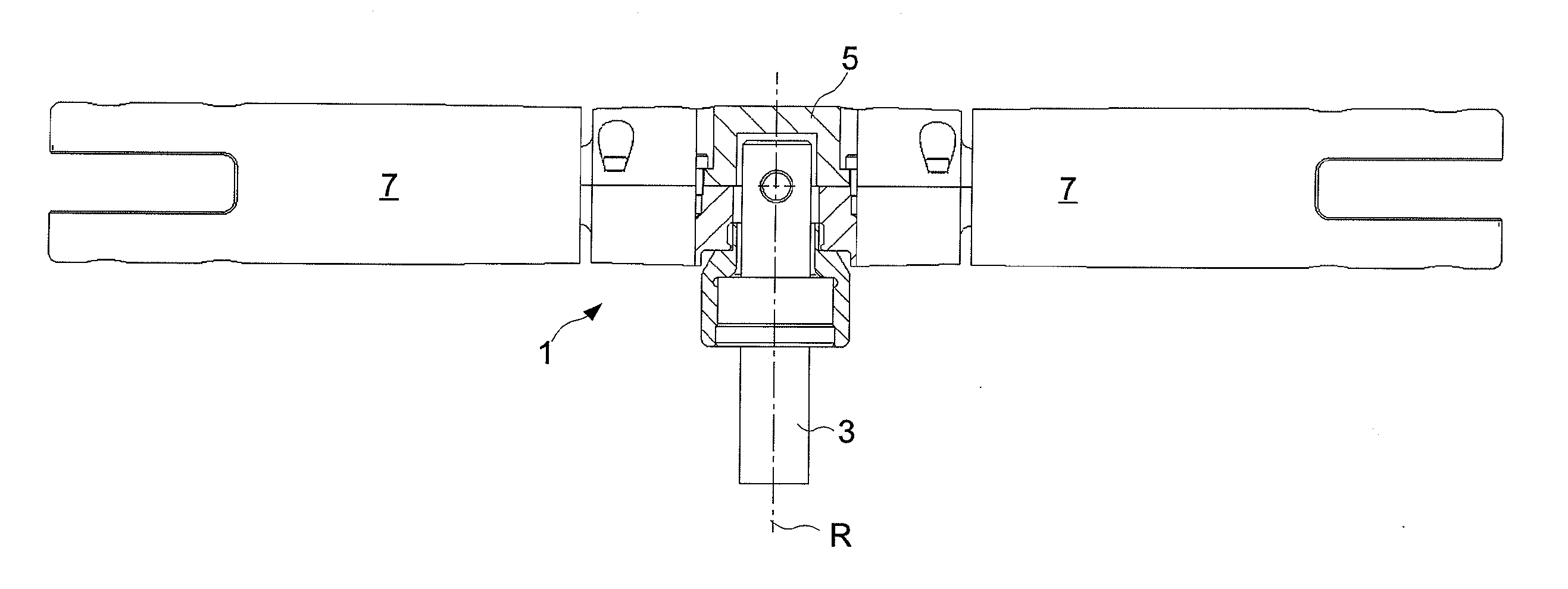
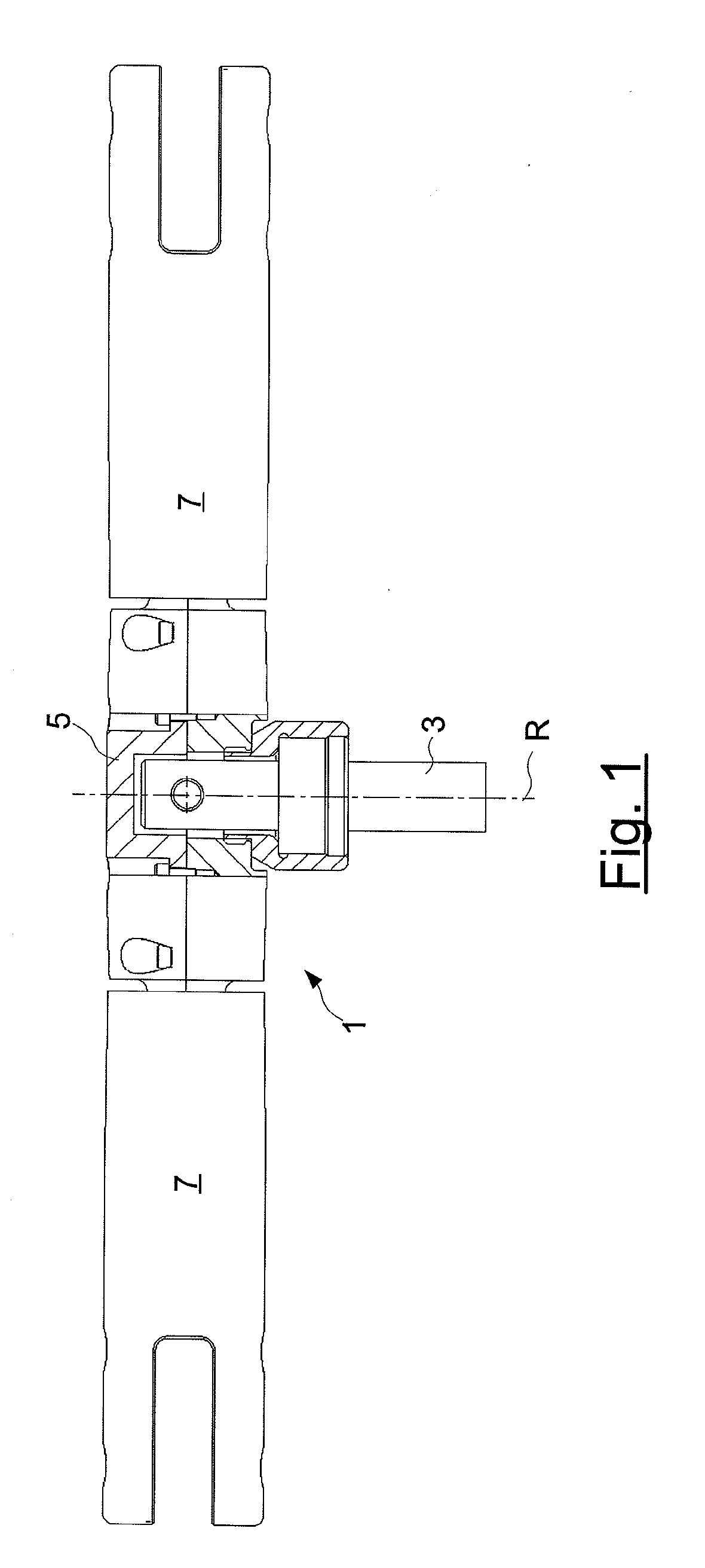
[0017]FIG. 1 shows a main rotor arrangement 1 of a not shown UAV-helicopter. The arrangement comprises a rotor mast 3 defining an axis of rotation R, a hub 5 and rotor blade holders 7 being attached to the hub 5.

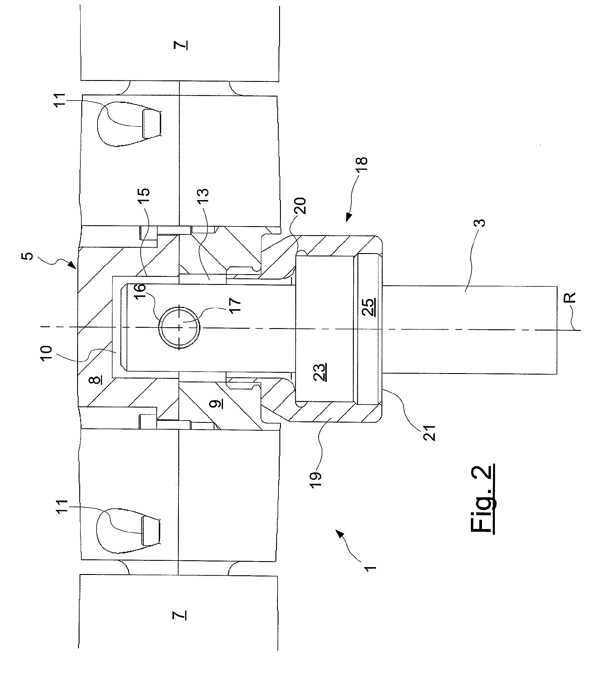
[0018]As seen in FIG. 2 the hub 5 comprises an upper hub half 8 and a lower hub half 9 which are joined by means of bolts 11. Both hub halves are hollow and together form a cylindrical inner space 10, which is defined by inner walls 15 of the hub halves. The inner space 10 has an inner diameter that is greater than the outer diameter of the rotor mast 3. The rotor mast comprises a pin extending through the rotor mast in a direction being perpendicular to the axis of rotation R. The hub halves are concentrically arranged on top of the rotor mast 3 whereby a circumferential uniform gap 13 is formed between the hub inner walls 15 and the periphery of the rotor mast 3. The hub 5 is suspended by the pin 17 by means of bearings 16, and the pin defines a horizontal pivot axis or te...


PUM


Abstract

A main rotor arrangement for an UAV-helicopter. A rotor mast defines a vertical axis of rotation. A hub is for attachment of rotor blades. The hub is mounted to the rotor mast in a tiltable way so as to reduce loads acting on the rotor blades during operation of the UAV-helicopter. A damping assembly is configured to damp the tilting of the hub.

Description

FIELD OF THE INVENTION[0001]The present invention relates to a main rotor arrangement according to the preamble of claim 1. The invention also relates to an UAV-helicopter comprising such an arrangement.BACKGROUND OF THE INVENTION[0002]The main rotor blades of an UAV-helicopter (UAV, Unmanned Aerial Vehicle) are subjected to loads during operation, e.g. pulsating bending forces which are transmitted from the rotor blades to the vertical rotor mast. The rotor mast is provided with a hub to which the rotor blades are mounted with the aid of rotor blade holders. One way of reducing the loads acting on the rotor blades is to make the hub tiltable so that the hub is allowed to deflect with respect to the rotor mast when subjected to said loads. As a result, the loads acting on the rotor blades can be reduced.[0003]Such main rotor arrangements are disclosed in U.S. Pat. No. 4,092,084 and U.S. Pat. No. 5,544,844. The disclosed solutions are provided with end stops so that the maximum defle...

Claims


Application Information

Patent Timeline
Patent Type & Authority Applications(United States)
IPC IPC(8): F04D29/32
CPCB64C27/43Y10S416/50B64C2201/024B64U10/10
Inventor CARDELL, PER-ERIKSTENBOM, KJELL
Owner SAAB AB
Why Eureka
Try Eureka