Vehicle seat

a technology for vehicles and seats, applied in the field of vehicles, can solve the problems of generating abnormal noise (collision noise) and the configuration of the disclosed technique, and achieve the effect of suppressing the generation of abnormal noise and suppressing damage to the respective webbing

Active Publication Date: 2017-06-27
TOYOTA BOSHOKU KK +1
View PDF13 Cites 4 Cited by
  • Summary
  • Abstract
  • Description
  • Claims
  • Application Information

AI Technical Summary

Benefits of technology

[0010]Thus, in the aspect of the invention, the mounting section is provided at a place where a body of the seat frame is disposed. When the airbag is uninflated, the mounting section holds the other ends of the pair of webbings apart from the body of the seat frame, and an inhibition portion provided in the mounting section inhibits contact between an edge-shaped portion formed in the body of the seat frame and each of the webbings. In the above aspect, the other ends of the pair of webbings are held apart from the body of the seat frame by the mounting section provided at the seat frame. Accordingly, it is possible to suitably suppress generation of abnormal noise caused by contact and separation between the body of the seat frame and the end portion (for example, a resin member on the end portion side) of each of the webbings. It is also possible to suitably suppress damage to the respective webbings by contact with the edge-shaped portion (for example, a relatively sharp portion formed by an end portion of a plate portion or a corner portion of a column) of the body of the seat frame by using the inhibition portion of the mounting section.
[0011]According to the above aspect, the vehicle seat further includes a seat pad that forms a seat outer shape, and elastically supports an occupant. The seat pad may have a main portion in the center that allows an occupant to be seated, and a bolster located lateral to the main portion, when the seat pad is disposed on the body of the seat frame and covered with the seat cover, the bolster may be supported on the body of the seat frame, and the mounting section may be provided so as to be gradually inclined in a direction toward the bolster from the main portion as the mounting section is separated from the disposed place. In the above configuration, by employing a configuration in which the mounting section is inclined toward the bolster so as to minimally project to the main portion side, a configuration in which sinking of an occupant into the main portion is minimally obstructed is achieved.
[0012]According to the above aspect, the mounting section may have a first engagement portion with which the first webbing is engageable, and a second engagement portion with which the second webbing is engageable, and the engagement portions may be disposed in a side frame of the seat frame. In accordance with the above configuration, disengagement of an engagement member caused when the engagement member is pressed by an occupant can be suitably avoided.
[0013]In accordance with the above aspect, the respective end portions of the pair of webbings can be effectively mounted to the seat frame. In accordance with the above configuration, the respective end portions of the pair of webbings can be more effectively mounted to the seat frame. Moreover, in accordance with the above configuration, the disengagement of the engagement member caused when the engagement member is pressed by an occupant can be suitably avoided.

Problems solved by technology

Thus, the disclosed technique has a configuration with slightly deteriorated seat performance due to repetitive contact and separation between the seat frame and the end portion of each of the band-shaped members.
That is, in the above configuration, when the seat frame and the hook are contacted with and separated from each other, abnormal noise (collision noise) may be generated.
Also, a body of the band-shaped member may be forcefully contacted with an end portion (an edge-shaped plate portion) of the seat frame, and may be thereby damaged.

Method used


Image

  • Vehicle seat
  • Vehicle seat
  • Vehicle seat

Examples


Embodiment Construction

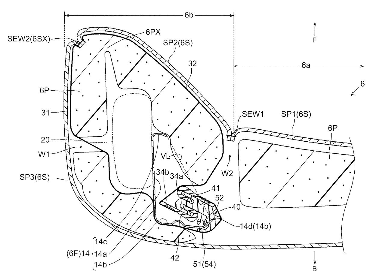
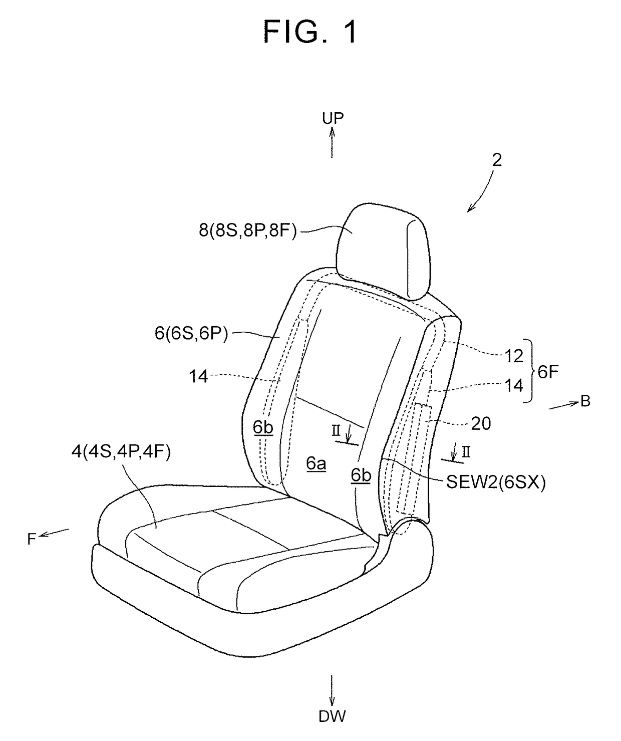
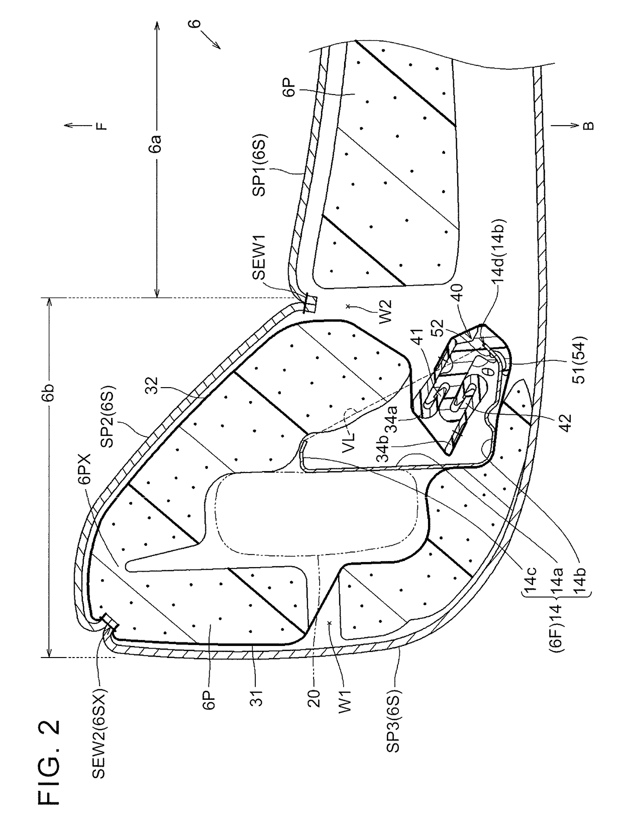
[0021]Hereinafter, an embodiment of the invention will be described by reference to FIGS. 1 to 6. In FIGS. 1, 2, reference character F denotes a front side of a vehicle seat, reference character B a rear side of the vehicle seat, reference character UP an upper side of the vehicle seat, and reference character DW a lower side of the vehicle seat as appropriate. A vehicle seat 2 in FIG. 1 includes a seat cushion 4, a seatback 6, and a headrest 8. The seat cushion 4, the seatback 6, and the headrest 8 (seat constituent members) include seat frames 4F, 6F, 8F that form a seat framework, seat pads 4P, 6P, 8P that form a seat outer shape, and seat covers 4S, 6S, 8S that cover the seat pads, respectively. The seatback 6 is connected to a rear portion of the seat cushion 4 so as to be reclinable. The headrest 8 is disposed on an upper portion of the seatback 6 (in an upright state).

[0022]The seatback 6 includes a basic configuration (6F, 6P, 6S), an airbag 20, and a relevant configuration ...


PUM


Abstract

A vehicle seat includes: a seat frame; a seat cover provided with a rupture portion; an airbag disposed in the seat; a pair of webbings provided so as to surround the airbag on a back surface side of the seat cover, one end sides of the webbings being mounted to the rupture portion; and a mounting section mounting the other end sides of the webbings to the seat frame. In a vehicle collision, the airbag is protruded out of the seat by rupturing and opening the rupture portion. The mounting section is provided at a place where a body of the seat frame is disposed. When the airbag is uninflated, the mounting section holds the other ends of the webbings apart from the body of the seat frame, and an inhibition portion in the mounting section inhibits contact between an edge-shaped portion formed in the body and the webbings.

Description

INCORPORATION BY REFERENCE[0001]The disclosure of Japanese Patent Application No. 2014-219429 filed on Oct. 28, 2014 including the specification, drawings and abstract is incorporated herein by reference in its entirety.BACKGROUND OF THE INVENTION[0002]1. Field of the Invention[0003]The invention relates to a vehicle seat including a seat frame, a seat cover, an airbag in the seat, and a pair of webbings.[0004]2. Description of Related Art[0005]As this type of vehicle seat, a vehicle seat including a seat frame, a seat pad, a seat cover, an airbag, and a deployment force concentrating cover has been disclosed (see U.S. Pat. No. 5,967,603). The seat frame is a metal frame body that forms a seat framework. A portion that forms a side framework has a plate shape (a substantially horizontal-U shape in sectional view). The seat pad is a member that forms a seat outer shape (typically made of foamed resin). The seat cover is a bag-shaped member that covers the seat pad. A seam that is eas...

Claims


Application Information

Patent Timeline
Patent Type & Authority Patents(United States)
IPC IPC(8): B60R21/207B60N2/42B60R21/217B60N2/58B60N2/90
CPCB60R21/207B60N2/42B60R21/2176B60N2002/5808
Inventor SAITO, TAKAOKONDO, KUNIHIKOYASUDA, TAKAHIROSHIGA, KAZUYUKI
Owner TOYOTA BOSHOKU KK
Why Eureka
Try Eureka