Structure for fastening metallic plate parts together

a technology for fastening parts and structures, applied in electrical apparatus casings/cabinets/drawers, couplings, electrical apparatus connections, etc., can solve problems such as abnormal vibration noise, structure cannot reduce the number of screws for fastening sheet metal parts together, etc., to prevent loosening of screw-fixed portions, reduce screw-fixing points, and enhance the ability of parts to be assembled and disassembled

Active Publication Date: 2012-09-25
MITSUBISHI ELECTRIC CORP
View PDF10 Cites 4 Cited by
  • Summary
  • Abstract
  • Description
  • Claims
  • Application Information

AI Technical Summary

Benefits of technology

[0005]However, the structure disclosed in Patent Document 1 aims at arranging the lower face member of the copy carrying path to be opened concurrently with the opening of the bottom plate; thus, the structure cannot reduce the number of screws for fastening sheet-metal parts together and further restrain generation of abnormal noise in vibration.
[0006]The present invention has been made to solve the above-mentioned problems, and an object of the present invention is to provide a structure that reduces screw-fixing points, and implements easily an assembly thereof by only hooking configurations, thus improving the ability of the structure to be assembled and disassembled. Further, another object of the present invention is to implement a cover fastening structure that prevents loosening of screw-fixed portions by normally applying thereon tension due to the hooking configurations after the assembly, and also restrains abnormal noise to be generated because of vibration or the like.
[0008]According to the present invention, the first sheet-metal and the second sheet-metal parts to be assembled and fixed to each other are arranged to be fastened to each other by the engagements between the hooking section and the hooking claw which are relatively provided in those parts and between the engaging hole and the engaging claw which are also relatively provided therein, thus enabling the two sheet-metal parts to be assembled together by reducing screw-fixing points, and further enhancing the ability of the parts to be assembled and disassembled.
[0009]Further, since the engagement faces between the hooking section and the hooking claw each have a taper formed thereon, such that the sheet-metal parts exert a pressing force on each other, after the assembly, the pressing force is normally exerted thereon, thereby preventing loosening of the screw-fixed portions and also suppressing abnormal noise to be generated due to vibration or the like.

Problems solved by technology

However, the structure disclosed in Patent Document 1 aims at arranging the lower face member of the copy carrying path to be opened concurrently with the opening of the bottom plate; thus, the structure cannot reduce the number of screws for fastening sheet-metal parts together and further restrain generation of abnormal noise in vibration.

Method used


Image

  • Structure for fastening metallic plate parts together
  • Structure for fastening metallic plate parts together
  • Structure for fastening metallic plate parts together

Examples


first embodiment

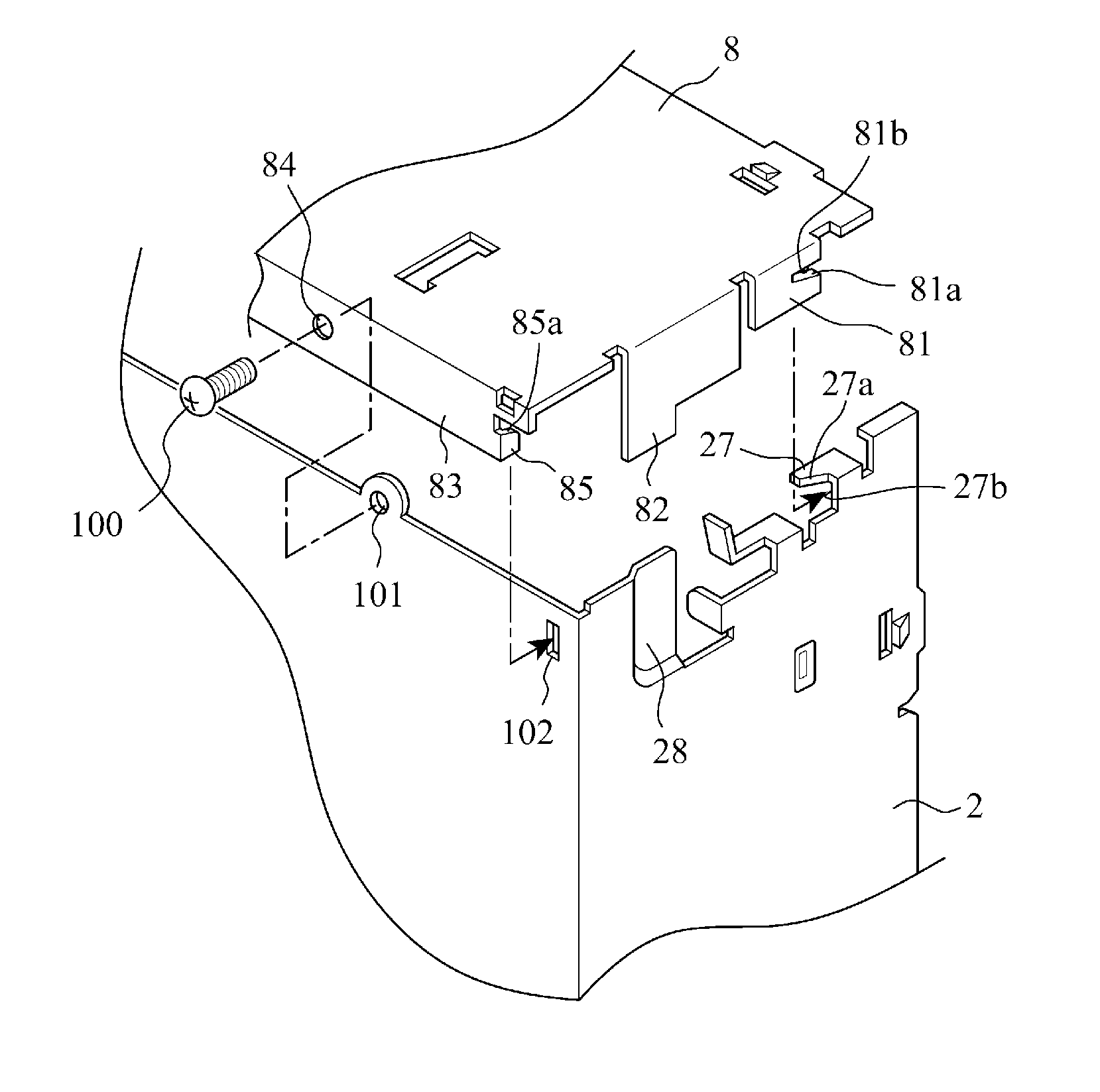
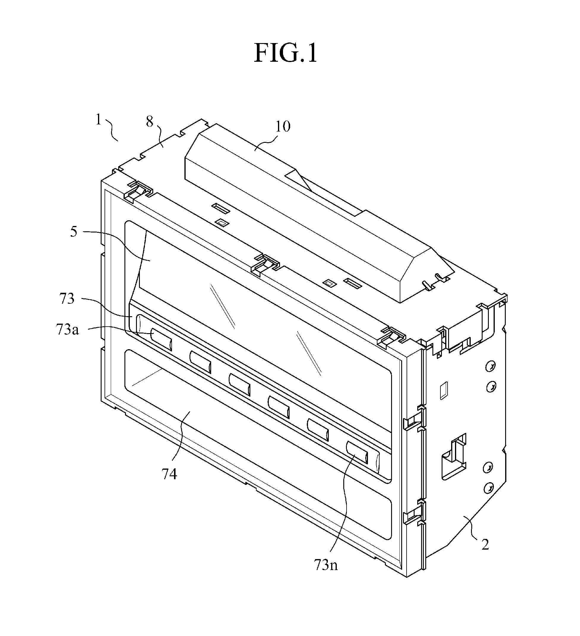
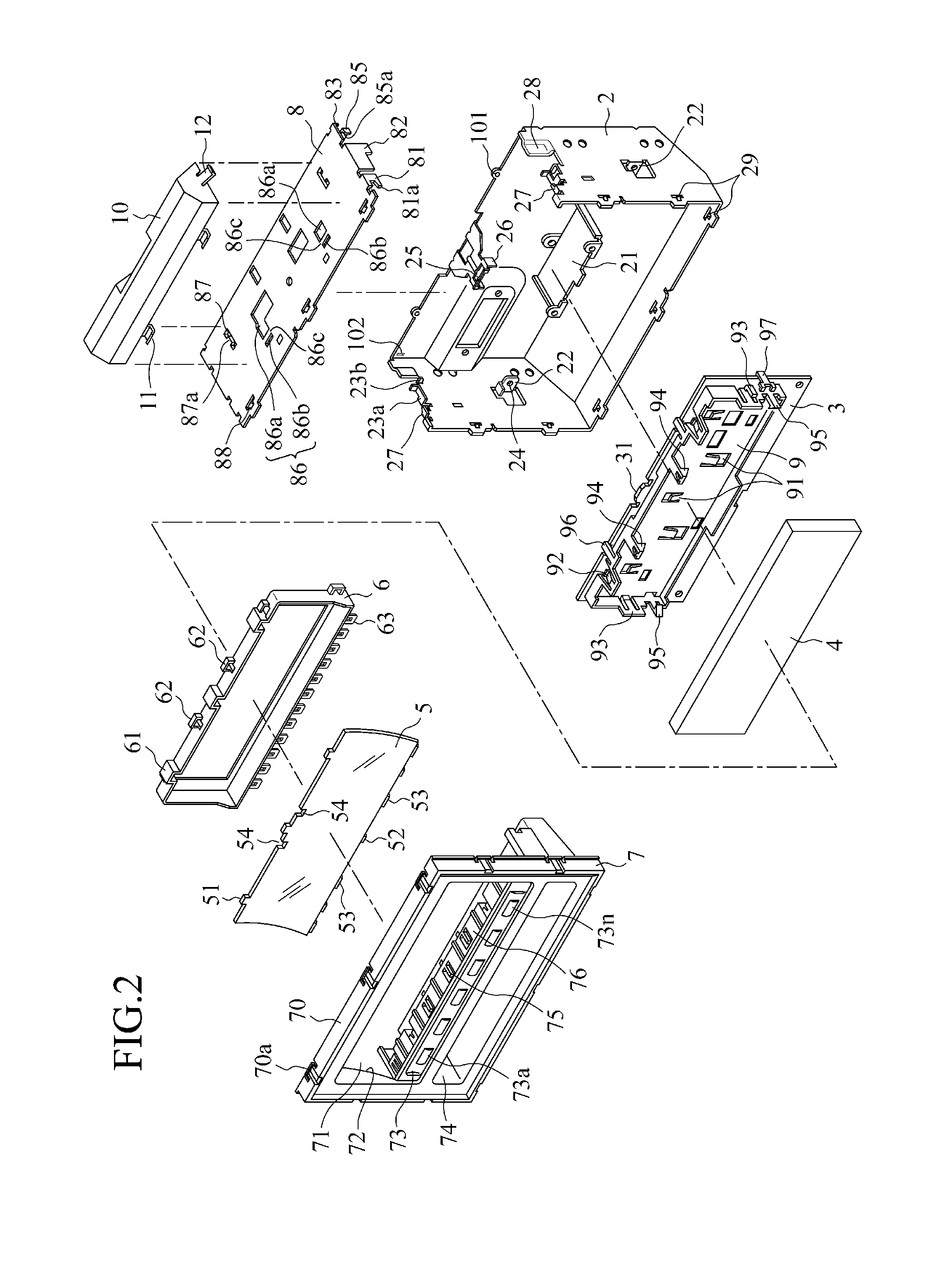
[0019]In the following, a structure for fastening sheet-metal parts together according to the present invention will be described with reference to the drawings. The outline of an electronic apparatus to which the structure for fastening sheet-metal parts together according to the present invention is applied will now be discussed with reference to FIG. 1 and FIG. 2. An electronic apparatus 1 includes: a box shaped hollow chassis 2 as a first sheet-metal part; a board 3 to be assembled to the interior of the chassis 2; a display 4 to be assembled to the board 3; a panel 7 to be assembled to the chassis 2, while a filter 5 disposed opposite the display 4 is attached thereto together with a hood 6; and a cover 8 as a second sheet-metal part for covering an opening of the chassis 2 after assembling all of these parts.

[0020]Note that in the following descriptions, expressions of “upper and lower side plates, ”“front and back side plates, ” and also “right and left side plates” are based...


PUM


Abstract

A chassis 2 as a first sheet-metal part has an L-shaped hooking section 27 formed at a cover mounting opening end of each side plate thereof, and an assembly guide section 28 dimpling inwardly the opening end of the chassis 2 by the thickness of a cover 8; the cover 8 as a second sheet-metal part has a hooking claw 81 extending from each side edge of the cover to the mounting side thereof and engaging with the L-shaped hooking section 27, and a guide lug 82 engaging with the assembly guide section 28, wherein an engaging claw 85 and an engaging hole 102, and a tapped hole 101 and a screw passing-through hole 84 are relatively provided on the abutment faces between the chassis 2 and the cover 8, respectively.

Description

FIELD OF THE INVENTION[0001]The present invention relates to a structure for fastening sheet-metal parts together for assembling a sheet-metal cover to a sheet-metal chassis in an electric apparatus.BACKGROUND ART[0002]In an electric apparatus mounted on a moving body such as a motor vehicle, for example, when a sheet-metal cover is assembled to a sheet-metal chassis, the chassis and cover, that is, two sheet-metal parts, are fixed together with screws. For this reason, a large number of screws are used, it takes a long time for the assembly, and the disassembly is also troublesome. Therefore, reduction of the number of the used screws is expected, which leads to reduction of the number of fastening points; thus, there is a problem such that abnormal noise is generated in vibration.[0003]On the other hand, an image forming apparatus of Patent Document 1 discloses an arrangement that in order to enable the interior of a copy carrying unit to be exposed from a lower face thereof at on...

Claims


Application Information

Patent Timeline
Patent Type & Authority Patents(United States)
IPC IPC(8): H01R13/502
CPCH05K5/0008H05K5/0013Y10T403/7015Y10T403/7045
Inventor HIROTA, HIDEYUKI
Owner MITSUBISHI ELECTRIC CORP
Why Eureka
Try Eureka