Metering feeder

a feeder and metering technology, applied in the direction of measuring devices, loading/unloading, instruments, etc., can solve the problems of affecting the accuracy of supply, dripping of powder/granular materials, etc., and achieve the effect of improving the filing efficiency of powder/granular materials, smooth transportation, and improving the filling efficiency

Active Publication Date: 2017-06-27
YOSHIKAWA KK
View PDF25 Cites 3 Cited by
  • Summary
  • Abstract
  • Description
  • Claims
  • Application Information

AI Technical Summary

Benefits of technology

[0009]The present invention has an object to provide a metering feeder which realizes highly accurate supply of a powder / granular material by providing a vertically-movable scraper for large supply and a fixed small scraper for small supply and by enabling the small supply of the powder / granular material only by the fixed small scraper in the small supply.
[0027]Moreover, since the powder / granular material to be newly discharged is filled on the powder / granular material remaining in the recessed portion, the powder / granular material can be easily filled into the powder / granular-material discharge groove on the return side, whereby filing efficiency of the powder / granular material can be improved.

Problems solved by technology

However, in the prior-art metering feeder, since the single powder / granular-material discharge scraper is used, “dripping” of the powder / granular material might occur when the rotating speed of the rotating disc is lowered for the small supply.
Moreover, it is likely that retention of the powder / granular material occurs on a return side of the rotating disc, or if filling of the powder / granular material in the powder / granular-material discharge groove is not sufficient, supply accuracy might be affected.

Method used


Image

  • Metering feeder
  • Metering feeder
  • Metering feeder

Examples


Embodiment Construction

[0044]A metering feeder according to the present invention will be described below in detail.

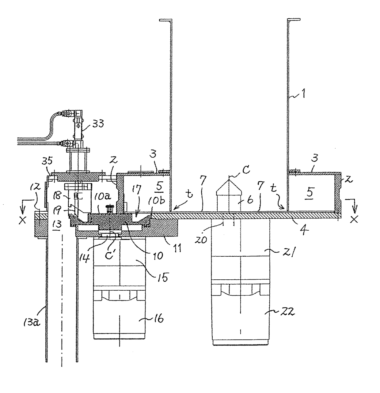
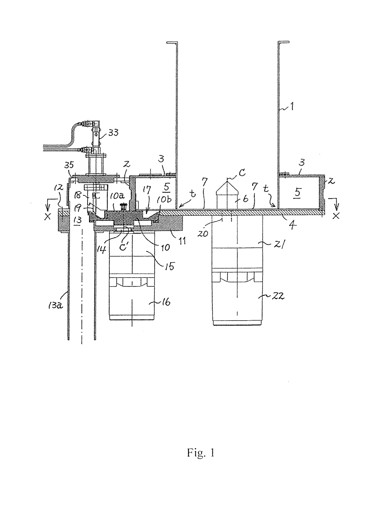
[0045]As illustrated, in FIGS. 1 and 2, upright circular inner and outer cylinders 1 and 2 sharing a center line C are provided integrally by a flange 3, and a bottom plate 4 is provided on the outer cylinder 2. A slight gap t is interposed between this bottom plate 4 and a lower end of the inner cylinder 1, an annular transport space 5 for a powder / granular material is formed between the inner and outer cylinders 1 and 2, and an upper end of an upright rotating shaft 6 is projected on the center line C of true bottom plate 4.

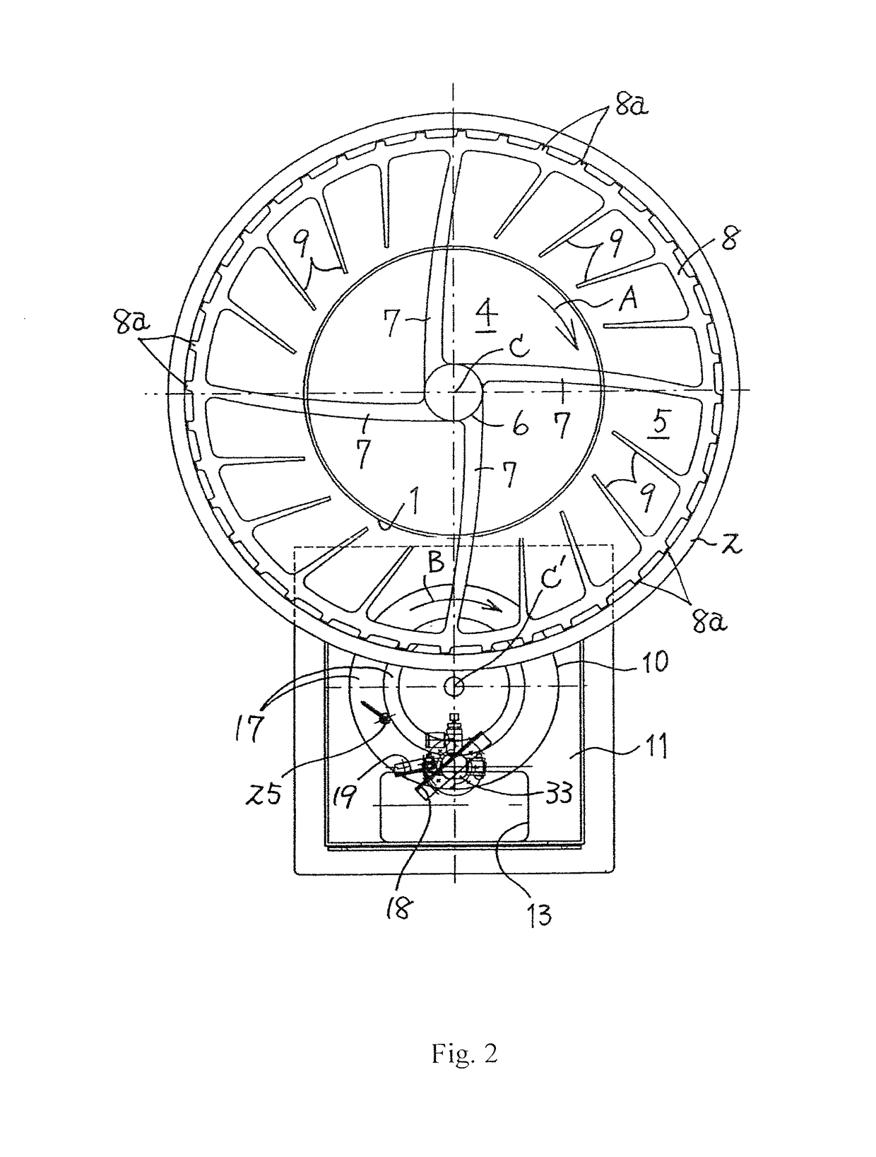
[0046]Base portions of a plurality (four pieces) of spoke-shaped central rotating blades 7 in contact with an upper surface of the bottom plate 4 are provided on the upright rotating shaft 6, a tip end of the rotating blade 7 is connected to an outer rotating ring 8 close to an inner peripheral surface of the outer cylinder 2 through the gap t, and a plurality of short ...


PUM


Abstract

A metering feeder is provided with the following: an annular transport space formed by an outer cylinder, an inner cylinder, and a bottom plate; a central rotating blade provided on a rotating shaft in the center of the bottom plate; an outer rotating ring connected to the tip of the central rotating blade; a plurality of outer rotating blades provided on the outer rotating ring so as to point inwards; and a rotating disc in which a powder / granular-material discharge groove is formed, the top surface of said rotating disc lying in the same plane as the top surface of the bottom plate. The outer rotating blades scrape the powder / granular material in the annular-transport space into the powder / granular-material discharge groove, which transports said powder / granular material outside the outer cylinder. This metering feeder is further provided with a vertically-movable scraper for supplying large amounts of the powder / granular material and a fixed small scraper for supplying small amounts thereof. Said scrapers block the flow of the powder / granular material in the powder / granular-material discharge groove in the rotating disc and guide same to a discharge opening. This configuration makes it possible to increase the precision with which the powder / granular material is supplied.

Description

TECHNICAL FIELD[0001]The present invention relates to a metering feeder for realizing highly accurate metering supply of a powder / granular material and the like.BACKGROUND OF THE INVENTION[0002]Conventionally, a metering feeder for metered supply of a material such as a powder / granular material or the like as illustrated in Patent Literature 1, for example, has been developed.[0003]This prior-art metering feeder has a configuration in which an inner cylinder and an outer cylinder are arranged concentrically, a gap is provided between a lower end of the inner cylinder and a bottom plate of the outer cylinder, whereby an annular transport space for a powder / granular material is provided between the inner and outer cylinders, a central rotating blade is provided on the bottom plate around a center upright rotating shaft of the bottom plate, an outer rotating ring along an inner periphery of the outer cylinder is provided at a tip end of the rotating blade, a plurality of outer rotating...

Claims


Application Information

Patent Timeline
Patent Type & Authority Patents(United States)
IPC IPC(8): G01F11/00B65G65/48G01F11/24
CPCB65G65/4836G01F11/24B65G65/4809B65G2201/042
Inventor YOSHIKAWA, OSAMUFURUKAWA, IZUMI
Owner YOSHIKAWA KK
Why Eureka
Try Eureka