Fire and water resistant expansion and seismic joint system

a seismic joint and expansion technology, applied in the field of joint systems, can solve the problems of subversion of fire resistive elements, deficiency of building joint systems in fire resistance, and pedestrian traffic to internal horizontal joints

Active Publication Date: 2017-06-27
EMSEAL JOINT SYST
View PDF432 Cites 69 Cited by
  • Summary
  • Abstract
  • Description
  • Claims
  • Application Information

AI Technical Summary

Problems solved by technology

However, interior horizontal joints may also be subject to pedestrian traffic and in some cases vehicular traffic as well.
It has been generally recognized that building joint systems are deficient with respect to fire resistance.
In some instances, movement as a result of building joint systems has been shown to create chimney effects which can have consequences with regard to fire containment.
This often results in the subversion of fire resistive elements that may be incorporated into the construction of a building.
This problem is particularly severe in large high-rise buildings, parking garages, and stadiums where fire may spread too rapidly to allow the structures to be evacuated.
Where movements were larger and the materials were significantly compressed during the normal thermal expansion cycles of the building structure, these designs generally did not function as intended.
Indeed, many designs simply lacked the resilience or recovery characteristics for maintaining adequate coverage of the entire joint width throughout the normal thermal cycle (expansion and contraction) that buildings experience.
These designs generally do not have fire resistant properties in a sufficient fashion to meet even the lowest fire rating standards.
Indeed, many waterproofing materials act as fuel for any fire present, which can lead to a chimney effect that rapidly spreads fire throughout a building.
Conversely, many fire rated expansion joints are not sufficiently water tight to render them suitable for exterior applications.
Many designs reliant upon mineral wool, ceramic materials and blankets, and intumescents, alone or in combination with each other, have compromised fire resistance by coming into contact with water.
Additionally, as noted above, many fire rated designs cannot accommodate the mechanical cycling due to thermal effects without compromising the fire resistance.
In many cases, there simply is not sufficient room in the physical space occupied by the expansion joint to accommodate both a fire rated system and a system capable of providing waterproofing or water resistance.
This is arguably another weakness, as an incorrectly installed or constructed system may compromise fire and water resistance properties.
In some cases, these fire resistant expansion joint systems do not employ cover plates and are instead invasively anchored to the concrete substrate.
Over time, the points at which such systems are anchored are subject to cracking and ultimately spalling, which may subvert the effectiveness of the fire resistance by simply allowing the fire to go around the fire resistant elements of the system.
Also, many expansion joint products do not fully consider the irregular nature of building expansion joints.
In many products, this is a point of weakness, as the homogeneous nature of the product is interrupted.

Method used


Image

  • Fire and water resistant expansion and seismic joint system
  • Fire and water resistant expansion and seismic joint system
  • Fire and water resistant expansion and seismic joint system

Examples


Embodiment Construction

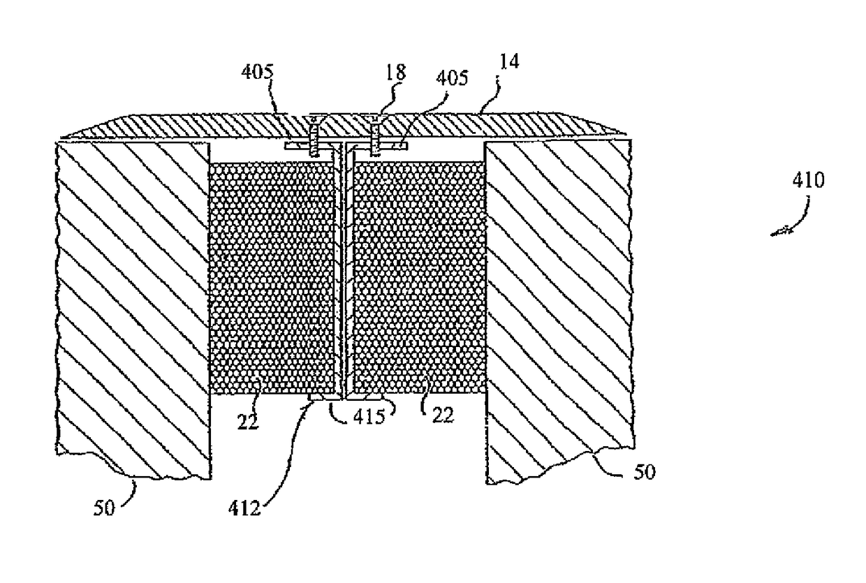
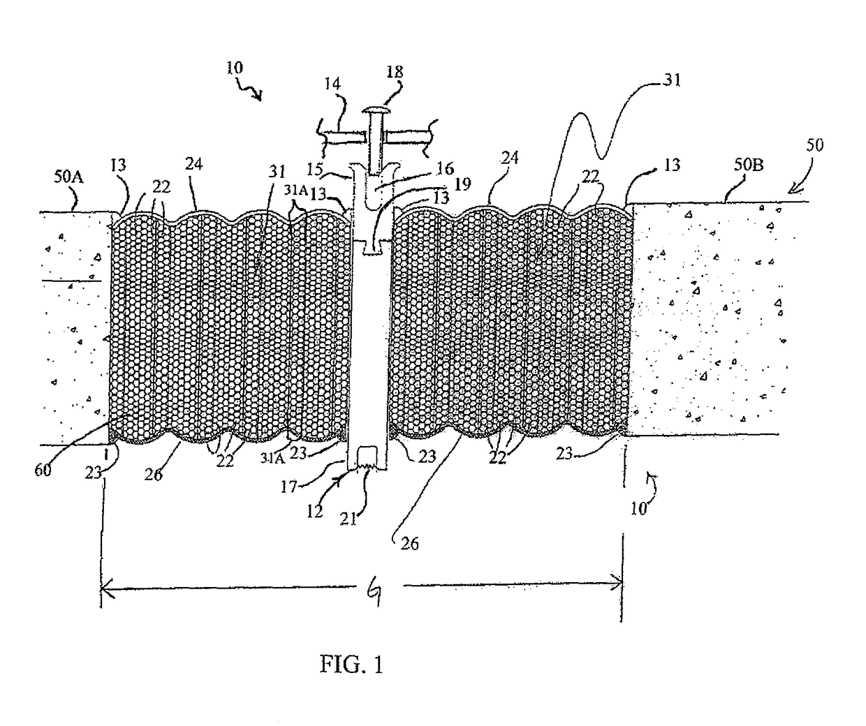
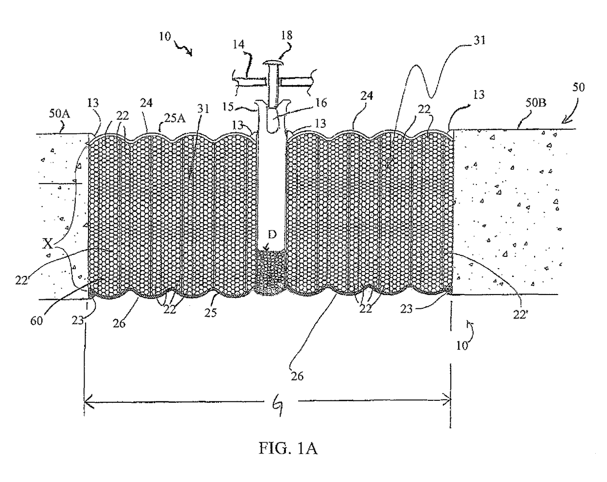
[0027]The expansion joint systems described herein can be understood by referring to the attached drawings and also to U.S. Pat. No. 6,532,708, which is incorporated by reference herein. One embodiment of an expansion joint system as described herein is installed between concrete substrates to define a concrete expansion joint system capable of accommodating movement of the concrete substrates due to thermal effects and / or seismic effects. The present invention is not limited in this regard, however, as the expansion joint system may be installed between substrates or surfaces other than concrete. Materials for such substrates or surfaces include, but are not limited to, glass, asphalt, stone (granite, marble, etc.), and the like. Furthermore, the expansion joint systems described herein are generally referred to as being horizontally oriented; however, the present invention is not limited in this regard, as the joint systems (with or without cover plates) can also be installed vert...


PUM

PropertyMeasurementUnit
temperatureaaaaaaaaaa
densityaaaaaaaaaa
temperatureaaaaaaaaaa

Abstract

A fire and water resistant expansion and seismic joint system has a cover plate; a spline attached to the cover plate along a first edge of the spline; and a core comprising a first core portion and a second core portion, each portion being located on an opposing face of the spline. The first core portion and the second core portion have a fire-retardant material infused therein. The spline depends from the cover plate in a one piece construction and extends into the core to a depth within the core, and is positioned in a gap between substantially coplanar substrates such that the cover plate overlies the gap. Each portion of the core is compressed between a respective face of the spline and a face of one of the coplanar substrates.

Description

CROSS REFERENCE TO RELATED APPLICATION[0001]This application is a Continuation Application of U.S. patent application Ser. No. 13 / 729,980, filed on Dec. 28, 2012, now U.S. Pat. No. 8,813,450, issued on Aug. 26, 2014, which is a Continuation-in-Part application of and claims priority to U.S. patent application Ser. No. 12 / 730,354, filed on Mar. 24, 2010, now U.S. Pat. No. 8,341,908, issued on Jan. 1, 2013, which claims the benefit of U.S. Provisional Patent Application No. 61 / 162,820, filed on Mar. 24, 2009, the contents of each of which are incorporated herein by reference in their entireties and the benefits of each are fully claimed.TECHNICAL FIELD[0002]The present invention relates generally to joint systems and, more particularly, to an expansion and seismic joint system that is fire and water resistant for use in building and construction applications.BACKGROUND[0003]Building and construction applications in which materials such as concrete, metal, and glass are used typically ...

Claims


Application Information

Patent Timeline
Patent Type & Authority Patents(United States)
IPC IPC(8): E04B1/68E04B1/94C09K21/00E04B1/98E04C2/20
CPCE04B1/68E04B1/94C09K21/00E04B1/948E04B1/98E04C2/20E04B1/6804E04B1/6812
Inventor HENSLEY, LESTERWITHERSPOON, BILL
Owner EMSEAL JOINT SYST
Why Eureka
Try Eureka