Arrangement and method for icing detection

a technology of icing detection and arrangement, applied in the field of measuring and optics, can solve the problems of increasing the risk of icing, blade cracking, wind turbine damage, etc., and achieves the effects of reducing the overall cost, facilitating the adoption phase, and controlling procedures

Active Publication Date: 2017-06-27
TEKNOLOGIAN TUTKIMUSKESKUS VTT
View PDF23 Cites 5 Cited by
  • Summary
  • Abstract
  • Description
  • Claims
  • Application Information

AI Technical Summary

Benefits of technology

[0008]The objective is to alleviate one or more problems described hereinabove not yet addressed by the known icing detection arrangements, and to provide a feasible solution for detecting atmospheric icing such as in-cloud icing.
[0034]The utility of the present invention arises from a plurality of issues depending on each particular embodiment. First of all, icing conditions may be predicted and detected preferably prior to the actual icing of the element of interest, such as the blades of the wind turbine, and the proposed icing detection method is reliable. Thus the required counter-procedures such as de-icing procedures or may be started as early as possible and further inconvenience or damage resulting from icing is advantageously overcome. Likewise, control procedures such as turbine control in the context of wind turbines may be enhanced by the knowledge of the prevalent icing conditions. Further, the existing equipment already installed at the destination sites, such as the lidars in conjunction with wind turbines or wind farms, may be applied to implement an embodiment of the present invention, whereupon the necessary additional gear remains moderately modest, which facilitates the adoption phase and reduces the overall cost.
[0035]Moreover, the suggested solution also enables estimating the likelihood of icing at several different distances relative to the reference point, which enables situating the arrangement farther away from the actual point of interest. For example, the lidar and optionally the processing entity may be conveniently provided to the nacelle of a wind turbine or even on the ground, while the conditions near the maximum altitude of the blade ends are still monitored.

Problems solved by technology

For example, in connection with aircrafts the ice may increase the risk of stalling of the airfoil.
As another use scenario, the wind turbines of wind farms may be heavily affected by ice on the rotor blades.
The blades may crack and the production efficiency may drastically decrease.
The overall wear of the turbine may also increase due to mass and aerodynamic imbalances and additional friction all caused by the ice.
However, e.g. the oscillation probe may not suit all use scenarios and may turn out too slow as to the achieved detection response.
It is relatively complex by nature and requires integration with the turbine nacelle.
The capacitance / impedance / inductance-based sensors may, on the other hand, work unreliably after the first detection as the ice removal from the sensor by heating, for example, may easily at least partially fail, whereupon the subsequent detections may be inaccurate.
Similar flaws have been recognized with many optical sensing solutions.
In summary, many known arrangements to detect icing still suffer from reliability problems at least in certain type of operational conditions.
Yet, their detection areas are limited as they represent only a single or few points in space, i.e. the sensor surface locations.
Even these solutions typically bear many weaknesses comparable to the ones already contemplated above.

Method used


Image

  • Arrangement and method for icing detection
  • Arrangement and method for icing detection
  • Arrangement and method for icing detection

Examples


Embodiment Construction

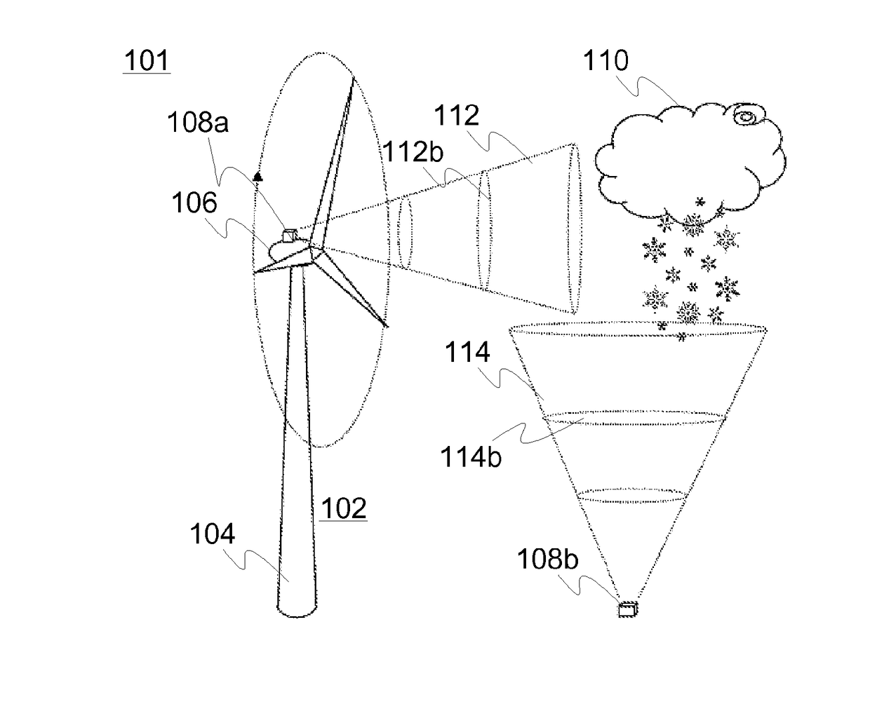
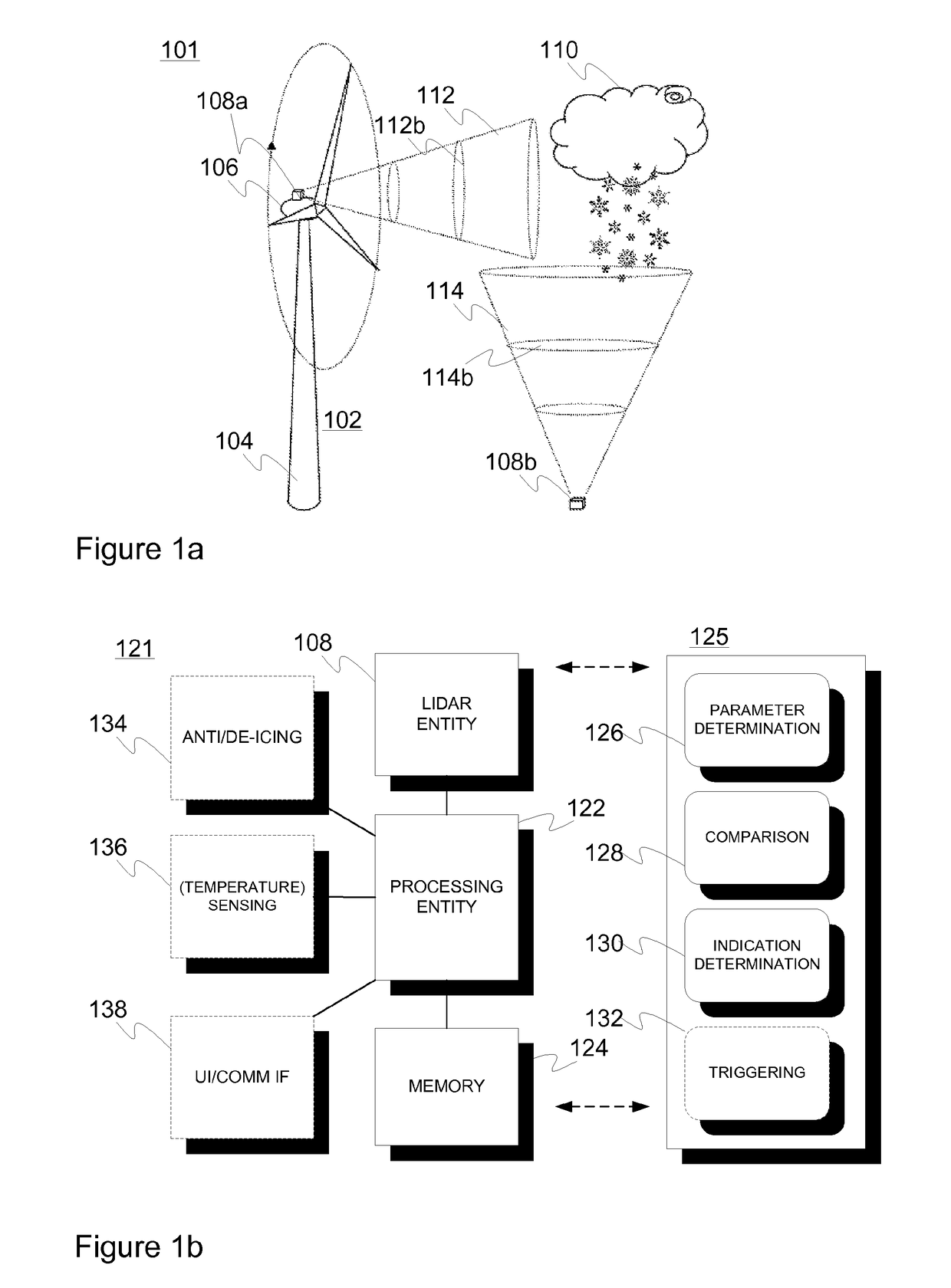
[0047]Lidars applied in connection with various embodiments of the present invention may incorporate laser-based devices capable to remotely measure the property of the atmosphere by sending laser beams in the air and then analyze the signal backscattered from the atmosphere. Lidars designed for wind energy applications can rather often measure the wind speed with high accuracy and precision regarding distances falling within a range from about 10 to about 1000 meters. They may be configured to measure the Doppler shift in the backscattered signal by the moving aerosol and can then possibly reconstruct the wind vector by probing a volume of air with at least three lines of sights. Such devices may allow, for instance, measuring the wind speed at the hub height of modern Multi-MW turbines for energy yield assessment with ground based instruments (staring upwards) but also for turbine control with nacelle mounted devices (staring horizontally). Measurements are not generally limited t...


PUM

PropertyMeasurementUnit
freezing pointaaaaaaaaaa
wavelengthaaaaaaaaaa

Abstract

A method for detecting atmospheric icing potential comprises emitting, by a Doppler lidar (light detection and ranging) entity, electromagnetic radiation to the atmosphere and receiving radiation backscattered from the aerosol, such as a cloud, present in the atmosphere. From the received backscattered radiation, an indication of the icing potential at a number of distances, on the basis of the comparison and an indication of the temperature at the one or more distances, is determined.

Description

FIELD OF THE INVENTION[0001]Generally the present invention pertains to measuring and optics. In particular, the invention is related to icing detection based on optical remote sensing.BACKGROUND[0002]Contemporary solutions for assessing the icing conditions of various surfaces and related elements differ considerably depending on the implementation and related use scenario.[0003]Atmospheric icing takes place when water droplets in the atmosphere freeze on a contacted object. For example, in connection with aircrafts the ice may increase the risk of stalling of the airfoil. Thereby, the ice built-up should be detected as early and reliably as possible. For instance, an electromechanical probe with an oscillating (vibrating) sensing element may be provided on the nose of the aircraft, whereupon the ice accreted thereon causes changes in the oscillation frequency depending on the thickness of the ice layer. The oscillation frequency is monitored for estimating the amount of ice.[0004]...

Claims


Application Information

Patent Timeline
Patent Type & Authority Patents(United States)
IPC IPC(8): G01W1/02G01S17/95G01N21/53G01W1/04G01S17/58G01N21/47G01N21/17
CPCG01W1/02G01N21/538G01S17/58G01S17/95G01W1/04G01N2021/1795G01N2021/4709Y02A90/10Y02E10/72G01N21/53G01S17/88
Inventor ANTIKAINEN, PETTERIVIGNAROLI, ANDREAPELTOLA, ESA
Owner TEKNOLOGIAN TUTKIMUSKESKUS VTT
Why Eureka
Try Eureka