Suture device

a technology of suture device and needle, which is applied in the field of needles, can solve the problems of cosmetic undesirable and substantial scarring, and achieve the effect of facilitating the change of direction of the shuttle member and precise control during the suturing procedur

Active Publication Date: 2013-08-20
AESTHETIC DEVICES
View PDF8 Cites 7 Cited by
  • Summary
  • Abstract
  • Description
  • Claims
  • Application Information

AI Technical Summary

Benefits of technology

[0029]The stop members typically comprise ramp-like structures. In this embodiment, the proximal or distal ends of the shuttle ride up the ramp until the shuttle is prevented from moving further in a longitudinal direction. When the shaft is moved in a different direction, the shuttle slides back down the ramp and travels longitudinally along said shaft. The ramp-like structure aids in preventing “sticking” of the shuttle on the stop member.
[0044]If using a metallic or other tethering member with radiopaque markers, a user may visualise the tethering member thus enabling precise control during a suturing procedure.
[0045]The shuttle member may be joined to the suture or tether by way of a universal joint. In one embodiment the joint may include a ball and socket joint. Alternatively, the joint may include a hinge arrangement. The universal joint may facilitate the change in direction of the shuttle member during use.
[0054]An advantage of the present needle assembly is that it enables the positioning of a suture(s) beneath the skin over a range of lengths without the requirement for individual incisions to position the suture(s). The only marks left on the patient are the elongate shaft entry and exit points which are far less likely to leave scarring.
[0069]The elastic properties of the abovementioned suture thread typically assists in a surgical procedure such as the cosmetic procedures outlined. For example, in a breast lift procedure the suture thread may be positioned using the assembly of the present invention such that it forms a lasoo type arrangement to lift the base of the breast upwardly. The elastomeric nature of the thread substantially prevents any trauma to the tissue during the lift and also provides for a more natural look of the breast post surgery. Particularly, the elastomeric nature of the suture thread allows a degree of stretch of the thread as the breast moves. Such an advantage enables a patient to enjoy a fuller life and to include activities such as running which would not be so comfortable with a non-stretch suture.
[0072]The suture thread, whether having elastic properties or not, may also include one or more barbs along its length. The barbs may lodge in the tissue and enhance a surgical procedure such as the cosmetic procedures discussed above. The barbs are preferably molded on the thread such that the risk of dislodgement in situ is minimised.

Problems solved by technology

The result of such suturing is substantial scarring which is, at the least, cosmetically undesirable.

Method used


Image

  • Suture device
  • Suture device
  • Suture device

Examples


Embodiment Construction

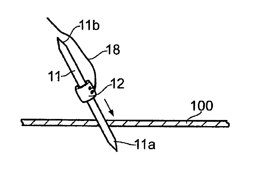
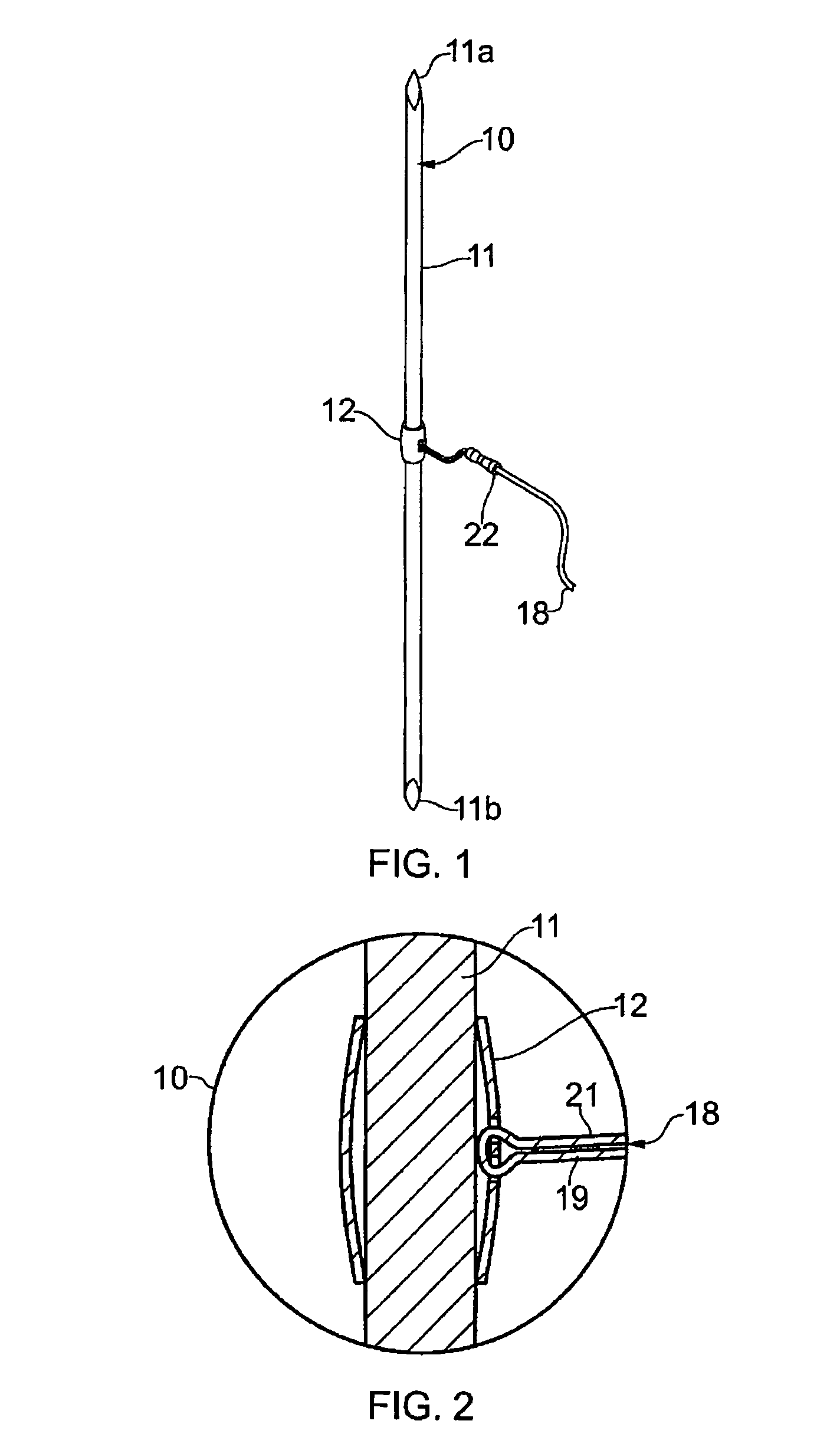
[0094]The needle assembly 10 of the present invention includes an elongate shaft 11 and a shuttle 12. The shaft 11 has two tapered ends 11a and 11b which are designed to pierce tissue. Typically the ends 11a and 11b are trocar tips.

[0095]The shuttle 12 is longitudinally moveable along a length of the shaft 11 and comprises a securing means to secure a suture 18 to the shuttle 12.

[0096]The shuttle 12 in addition to being longitudinally moveable along a length of the elongate shaft 11 is also fully rotatable relative to said shaft 11.

[0097]In the embodiments depicted, the shuttle 12 is positioned outside the shaft 11. The shaft in the embodiments depicted in FIGS. 1 to 6 is a solid structure which provides a stiffer structure at any given diameter than a needle shaft with either an eye or having a slot to receive a shuttle 12.

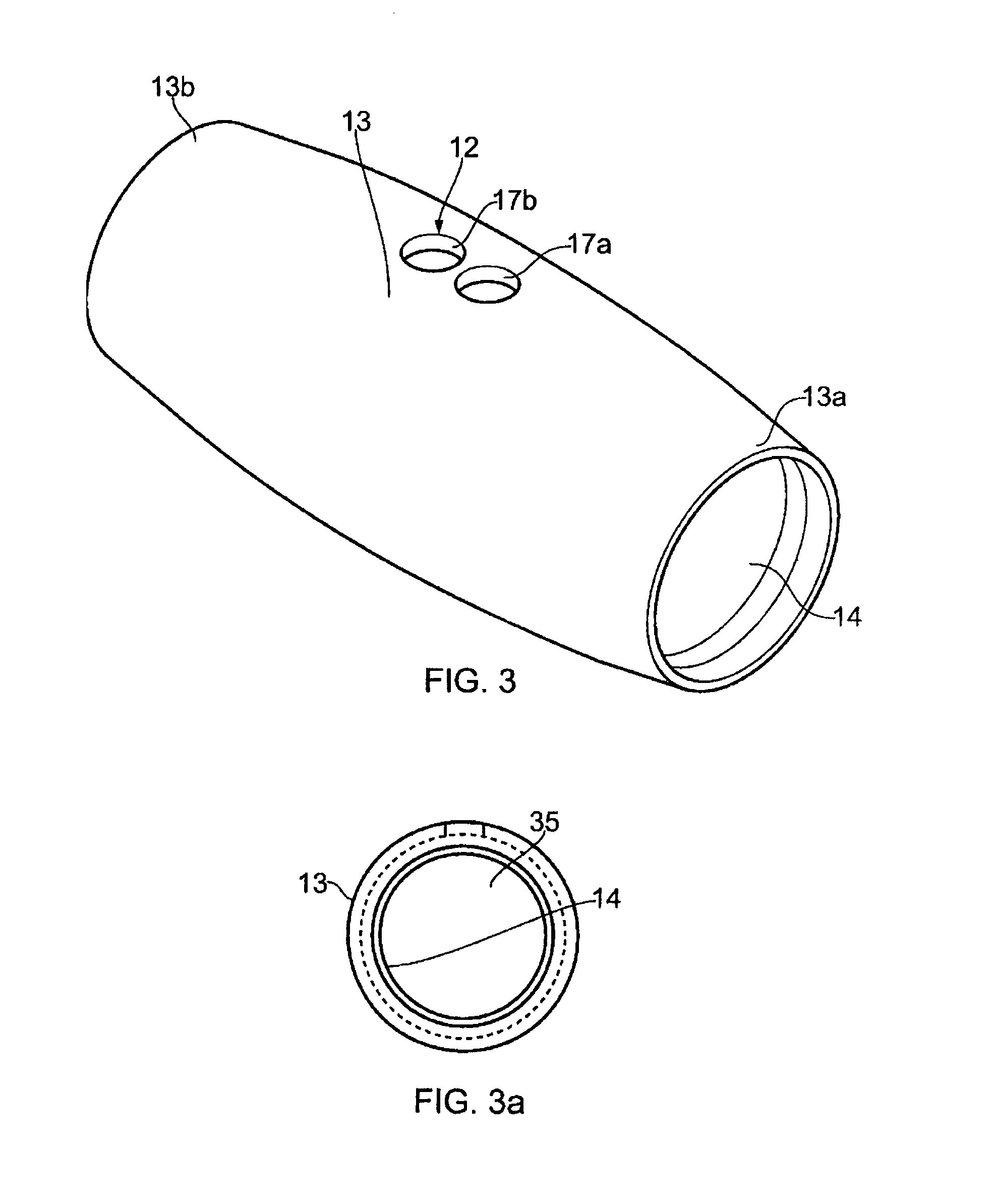
[0098]The shuttle 12 is depicted in FIG. 3 as a substantially tubular body 13 extending from a proximal end 13a to a distal end 13b. An inner wall 14 defines a l...


PUM


Abstract

A needle assembly comprises a shaft with two opposite tissue piercing ends. The assembly includes a shuttle which is moveable relative to the shaft between the two ends. The shuttle comprises means to secure a suture to the shuttle member.

Description

FIELD OF THE INVENTION[0001]The present invention relates to needles and particularly to medical suture needle assemblies.BACKGROUND ART[0002]Many types of needles are available for a variety of surgical indications, ranging from simple closure of surface wounds to complex anastomoses and repair of various tissues.[0003]In a most basic form, sutures are attached to a needle through an eye located at one end. Following puncture through the skin and tying of an end, the needle travels subcutaneously to an exit point whereupon both the needle and trailing suture are pulled through the skin. The suture is tied at the exit point and the steps repeated as required. The result of such suturing is substantial scarring which is, at the least, cosmetically undesirable.[0004]In WO2007 / 098535, a double tipped needle with an elongate lumen is disclosed. The suture attached to this needle moves along the elongate lumen to enable a surgeon to manipulate the needle to retain a suture subcutaneously...

Claims


Application Information

Patent Timeline
Patent Type & Authority Patents(United States)
IPC IPC(8): A61B17/06
CPCA61B17/06066A61B2017/0609A61B2017/06047A61B2017/00893
Inventor GILSON, PAULWHITE, GEOFFREY H.DAOOD, JASSIM
Owner AESTHETIC DEVICES
Why Eureka
Try Eureka