
Light fixture with air handler

a technology of light fixture and air handler, which is applied in the field of light fixtures and fan/light units, and can solve problems such as no means for warming the air

Inactive Publication Date: 2017-07-04
HARDGRAVE ERIC NEAL
View PDF4 Cites 39 Cited by
  • Summary
  • Abstract
  • Description
  • Claims
  • Application Information

AI Technical Summary

Benefits of technology

The patent describes a fan and light unit that can be placed in a variety of ways to provide both aesthetic lighting and directed air flow. The fan and light are separate units that can be controlled individually or collectively. The unit also includes heater strips to warm the air and filters to clean the air as it passes through the air handler. The technical effects of this design are efficient air movement and warm, clean air.

Problems solved by technology

Ceiling fans typically move air to cool a room, and provide no means for warming the air.

Method used


Image

  • Light fixture with air handler
  • Light fixture with air handler
  • Light fixture with air handler

Examples


Embodiment Construction

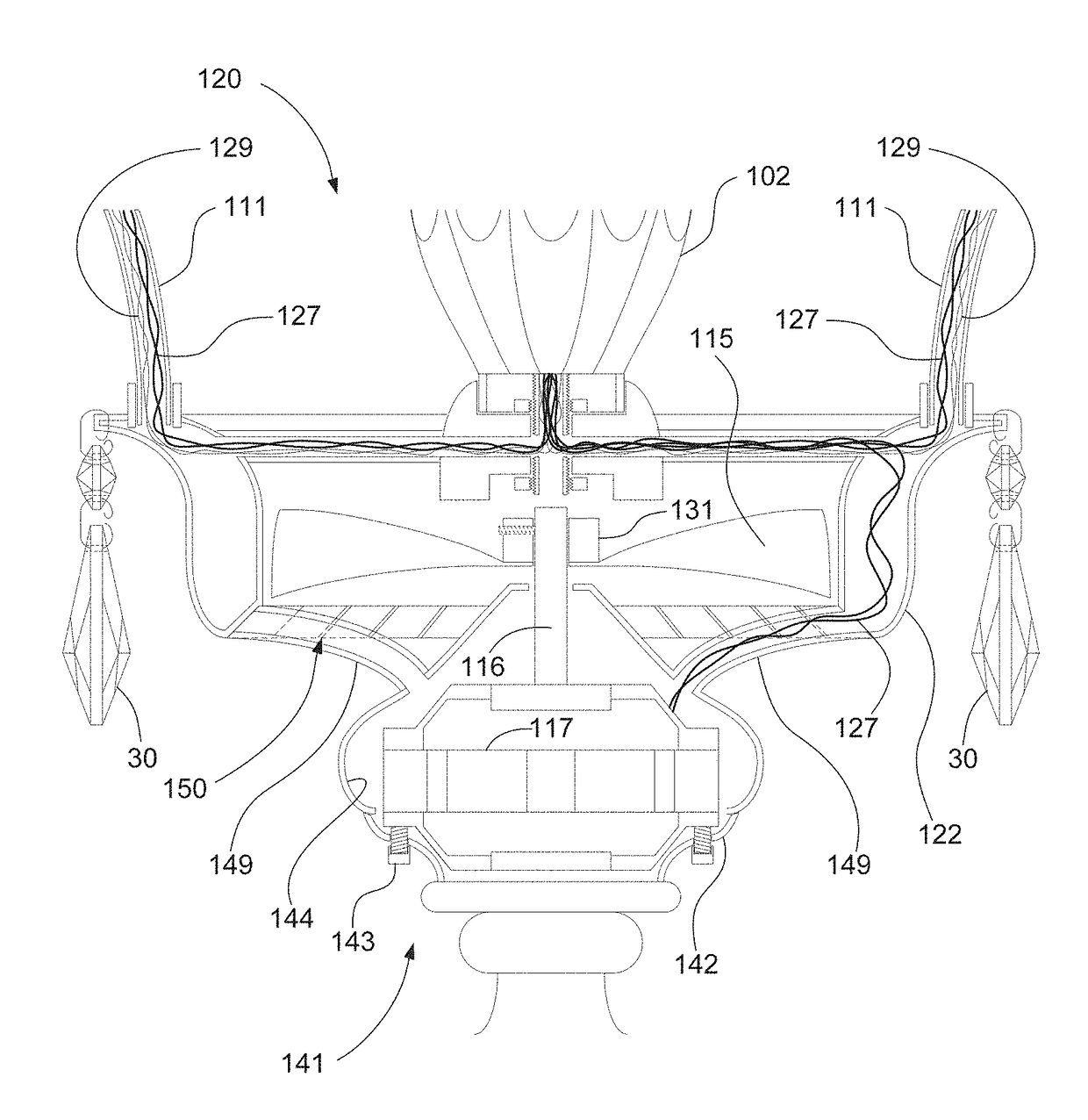
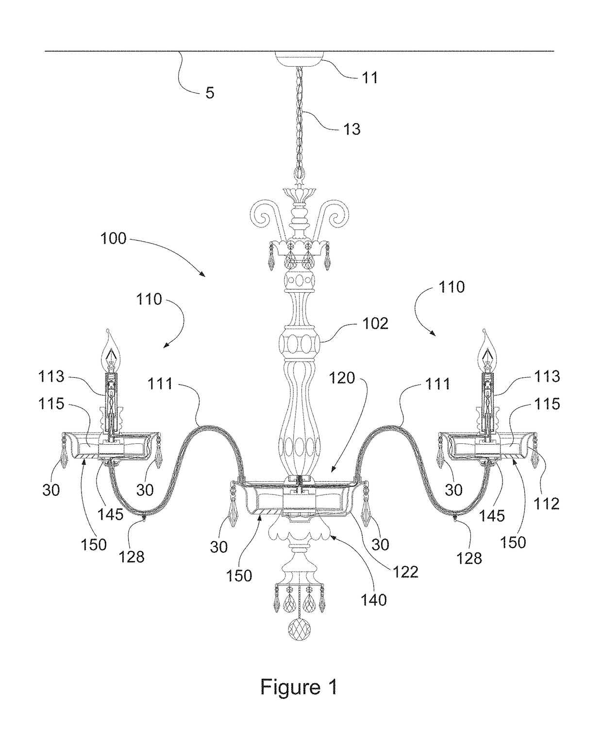
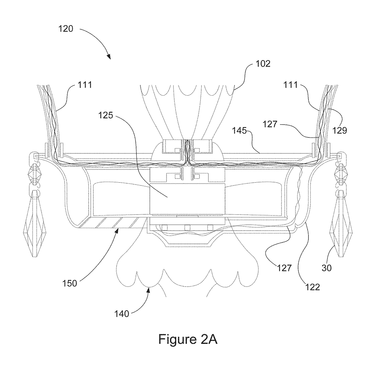
[0036]With reference now to the figures, and in particular to FIGS. 1-5B, fan chandelier 100 comprises central body 102 depending from ceiling 5 at mount 11 by suspension means 13 (such as a chain or rigid mast). Disposed at the bottom of central body 102 opposite chain 13, central fan unit 120 includes shroud 122 encircling fan 125 and supporting the ends of arms 111 proximate central body 102. Base 140 depending from fan unit 120, discussed in more detail below, serves in part to disperse air flowing downward from fan 125.

[0037]As seen best in FIG. 4A, fan chandelier 100 further comprises a plurality of satellite units 110 arrayed radially on arms 111 and evenly encircling central body 102 above dining table 1 and seating 3. Satellites 110 also may be disposed in more than one plane (fan chandelier 105 in FIG. 5A) and at different radial distances from central body 102. Each of satellites 110 is supported by base 145 or 146 disposed at the end of arm 111 opposite central body 102....


PUM


Abstract

A combination fan and light unit comprises a housing surrounding a coaxial fan disposed such that air impelled by the fan passes through the housing and is directed as desired by orienting the housing or by diffusers disposed across the air path. Disposed above and / or below the housing, a light optionally enclosed within a globe coupled to the housing also provides illumination from the fan light unit. Fan light units may be arrayed in various configurations, including single or multiple sconce arrays supported on walls, one or more pendant fan lights suspended from ceilings, satellite fan lights arrayed around a central body at the ends of radial arms to form a fan chandelier or in many other configurations to achieve both aesthetic lighting and directed air flow. The fan lights preferably have separate controls, and multiple units in a collective array such as a fan chandelier may be individually or collectively controllable. The fan light units may include heater strips to warm the air and filters to clean the air as it passes through the air handler.

Description

[0001]This application is a Continuation Application of application Ser. No. 12 / 856,044 filed on Aug. 13, 2010, which is a Continuation-In-Part of application Ser. No. 11 / 378,209 filed on Mar. 16, 2006, now issued as U.S. Pat. No. 7,819,563, which is a non-provisional application of Provisional Application Ser. No. 60 / 663,479 filed Mar. 16, 2005, all of which are hereby incorporated by reference to the maximum extent permitted by law.BACKGROUND OF THE INVENTION[0002]1. Field of the Invention[0003]This invention relates generally to light fixtures, and particularly to light fixtures having built-in air handlers to provide both light and air movement in a single fixture. More particularly, this invention relates to a fan / light unit having one or more light sources and a shrouded air handler for dispersing both light and air movement within a selected area.[0004]2. Description of Related Art[0005]Chandeliers comprise decorative, sometimes exceptionally attractive lighting fixtures usua...

Claims


Application Information

Patent Timeline
Patent Type & Authority Patents(United States)
IPC IPC(8): F21V33/00F24F8/108F24F8/158
CPCF21V33/0096F21S8/036F21S8/065F21W2131/30F24F2221/02F21V5/06F24F8/158F24F8/108F21V33/0092F21S8/04F21V21/104F04D25/088
Inventor HARDGRAVE, ERIC NEAL
Owner HARDGRAVE ERIC NEAL
Learn More