
Cyber security for physical systems

a physical system and cyber security technology, applied in the field of cyber security systems and methods, can solve the problems of new vulnerabilities and susceptibilities of controlling and controlled equipment to be operated in an unwanted manner

Active Publication Date: 2017-07-04
MISSION SECURE INC
View PDF4 Cites 60 Cited by
  • Summary
  • Abstract
  • Description
  • Claims
  • Application Information

AI Technical Summary

Benefits of technology

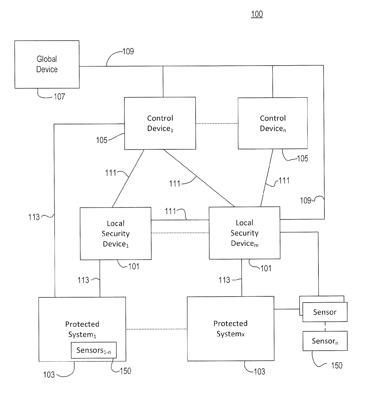
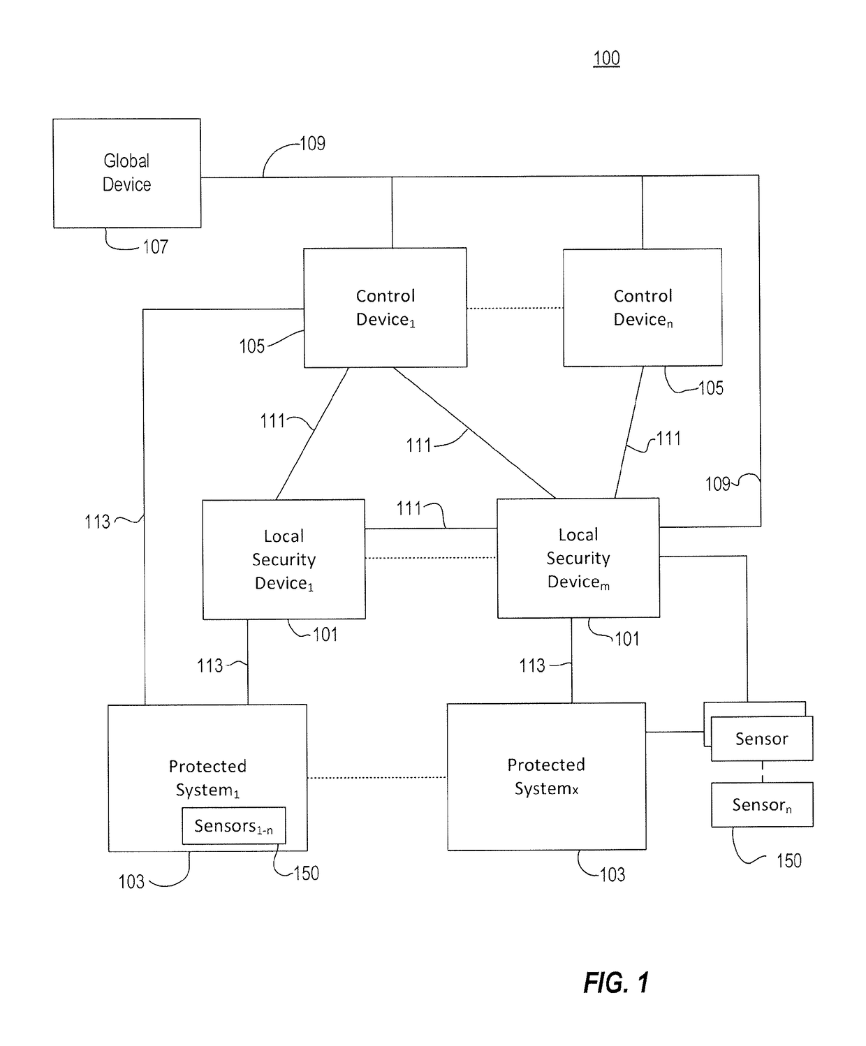
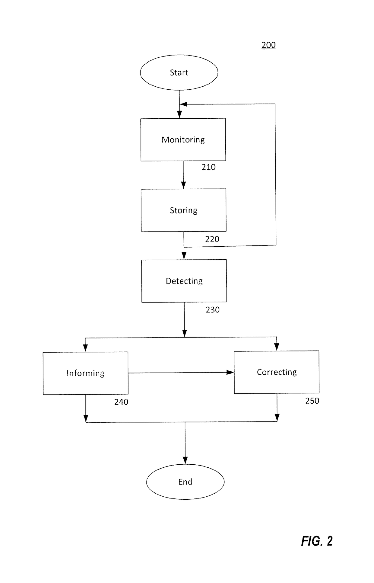
The patent text describes a cyber security system that can detect and correct unwanted operating conditions or modes in a protected system or device. The system includes one or more local security devices that monitor operational aspects of the system and can identify potential cyber attacks. The system can also include a control device that receives information from the local security devices and analyzes it to determine if there is a security condition that requires a response. The system can be embedded in the protected system or device and can communicate securely with external sources. The technical effect of the invention is to provide a system that can detect and correct cyber security threats in real-time, ensuring the continued operational awareness and effectiveness of the protected system or device.

Problems solved by technology

The increasingly ubiquitous use of computers and processors for controlling equipment and systems has led to new vulnerabilities and susceptibilities of the controlling and controlled equipment to be operated in an unwanted manner due to, for example, hacking and other malicious or unauthorized access for command and control of the affected systems.

Method used


Image

  • Cyber security for physical systems
  • Cyber security for physical systems
  • Cyber security for physical systems

Examples


Embodiment Construction

[0011]Embodiments relate generally to a cyber security system comprising at least one component, either a first or a second component, adapted to be coupled to a secured system, and may further include additional first or second components with the second component or components operatively coupled to one or more of the first components configured to monitor, control, and interact with the one or more first components based on sensed information received from the one or more first components, and a third component configured to receive information from and to monitor at least one of the second components or one or more first components as well as one or more of the third components to analyze the sensed information and the security information to determine global operational awareness. The second component is further configured to output security information to a user and to the third component. However, in some embodiments, the first component can also output security information t...


PUM


Abstract

A cyber security system and method that includes one or more devices configured to determine a cyber security threat or breach event based on analysis of operational information of a protected system.

Description

FIELD OF THE INVENTION[0001]Embodiments relate generally to cyber security systems and methods and, in particular, to systems and methods for detecting and correcting unwanted operating conditions or modes.BACKGROUND OF THE INVENTION[0002]The increasingly ubiquitous use of computers and processors for controlling equipment and systems has led to new vulnerabilities and susceptibilities of the controlling and controlled equipment to be operated in an unwanted manner due to, for example, hacking and other malicious or unauthorized access for command and control of the affected systems. There is also an increasing likelihood of such systems being provided in networked communications, and the advent of control being provided at ever more minute levels. Especially important is the ability of the affected system to continue to operate with minimized disruptions or effectiveness in the presence of a cyber security threat or breach of the system.BRIEF DESCRIPTION OF THE DRAWINGS[0003]Embodi...

Claims


Application Information

Patent Timeline
IPC IPC(8): G06F11/20G06F21/55G06F12/16G08B23/00G06F12/14
CPCG06F21/552G06F21/554G06F2221/034
Inventor PARK, DANIEL D.BRABEC, FRANTISEKJONES, RICK A.SUHLER, EDWARD C.DRESCHER, DAVID R. M.PERNOTTO, EDWARD P.
Owner MISSION SECURE INC
Learn More