Method of transmitting data in a communication system

a communication system and data technology, applied in the field of communication system transmitting and receiving data, can solve the problems of increasing the power consumption of the terminal, increasing the introduction of packet loss and delay, and requiring large amounts of data to be encoded and transmitted via the communication network, so as to achieve the acceptable level of image quality and improve the resolution of the imag

Active Publication Date: 2017-07-04
MICROSOFT TECH LICENSING LLC
View PDF75 Cites 3 Cited by
  • Summary
  • Abstract
  • Description
  • Claims
  • Application Information

AI Technical Summary

Benefits of technology

[0030]One advantage of embodiments of the present invention is that the resolution of the image may be adapted to increase only when this is necessary to maintain an acceptable level of quality of the displayed image.

Problems solved by technology

The transmission of high quality images, such as those with a high resolution, may require large amounts of data to be encoded and transmitted via the communication network, particularly during real time communication events such as video calls and video streaming.
This consumes a large amount of CPU (Central Processing Unit) resource of the transmitting terminal and of the receiving terminal which in turn increases the power consumption of the terminals.
The transmission of large amounts of data will also consume the bandwidth of network, thereby increasing introducing packet loss and delay.
The transmission of high quality images may require complex compression methods to encode the data, such encoding methods may again consume a large amount of CPU resource.
A further problem with transmitting high quality images is that this can overload the CPU resources of the terminals thereby adversely affecting the operation of the terminal to display the image and perform other processing functions.
However this can also adversely affect the quality of the displayed image.

Method used


Image

  • Method of transmitting data in a communication system
  • Method of transmitting data in a communication system
  • Method of transmitting data in a communication system

Examples


Embodiment Construction

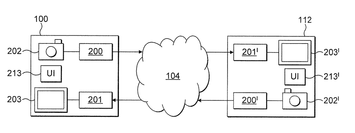
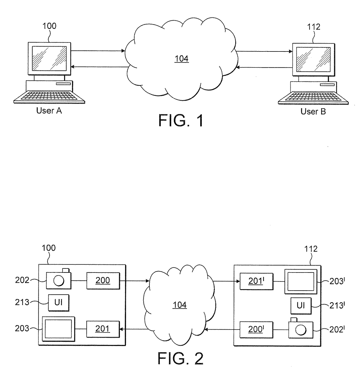
[0046]FIG. 1 shows a first node 100 and a second node 112 connected to a communication network 104. In the described embodiment, the first node 100 is a first user terminal operated by User A, and the second node 112 is a second user terminal 112 is operated by User B. In an alternative embodiment the first node 100 may be a server arranged to provide media content to the user terminal 112. In one embodiment of the invention the communication network 104 is the internet.

[0047]The user terminals 100, 112, may be a personal computer, a gaming device, a personal digital assistant, a suitably enabled mobile phone, a television, or another device able to output image data on an integrated or peripheral display. The terminals may be connected to the network via a wired or wireless connection that employs a particular access technology such as Ethernet, WiFi, WiMax (Worldwide Interoperability for Microwave Access), or 3G (third generation).

[0048]A communication event, such as a video call,...


PUM


Abstract

A method of transmitting image data from a first node to a second node during a communication event, wherein the second node comprises a display for displaying image data at the second node, includes receiving at the first node, information indicating at least one display characteristic with which image data received at the second node will be displayed on the display; inputting image data at the first node; determining a processing step to be applied to the inputted image data to generate adapted image data, such that at least one characteristic of the adapted image data is optimized for the at least one display characteristic; applying the processing step to generate the adapted image data; and transmitting the adapted image data to the second terminal.

Description

RELATED APPLICATIONS[0001]This application claims priority under 35 U.S.C. §119 or 365 to Great Britain Application No. 0819389.8, filed Oct. 22, 2008 and PCT / IB08 / 001353, filed Mar. 12, 2008. The entire teachings of the above applications are incorporated herein by reference.FIELD OF THE INVENTION[0002]The present invention relates to a method and system for transmitting and receiving data in a communication system. More particularly, the present invention relates to a method and apparatus for transmitting and receiving image data to be output to a user on a display.BACKGROUND OF THE INVENTION[0003]In a communication system a communication network is provided, which can link together at least two communication terminals so that the terminals can send information to each other in a call or other communication event. Information may include speech, text, images or video.[0004]Digital communication systems are based on the transmission of digital signals. Analogue signals such as ligh...

Claims


Application Information

Patent Timeline
Patent Type & Authority Patents(United States)
IPC IPC(8): G06F15/16H04L12/801H04L12/825H04L12/811H04L12/815H04L12/26H04L47/22
CPCH04L47/26H04L43/0894H04L47/10H04L47/22H04L47/263H04L47/38H04L43/0858
Inventor JEFREMOV, ANDREIWURM, KARLHEINZ
Owner MICROSOFT TECH LICENSING LLC
Why Eureka
Try Eureka