Projectile with enhanced ballistics

a projectile and enhanced technology, applied in the field of projectile devices, can solve the problems of reducing reducing the accuracy and velocity of targets, and reducing the accuracy of targets, so as to improve the penetration rate of targets, enhance the spin of bullets in flight, and improve the effect of external ballistics

Active Publication Date: 2017-07-18
G9 HLDG LLC
View PDF83 Cites 184 Cited by
  • Summary
  • Abstract
  • Description
  • Claims
  • Application Information

AI Technical Summary

Benefits of technology

[0011]What is needed is a projectile that does not substantially degrade in flight characteristics once leaving the gun barrel, so as to achieve flatter and faster external ballistics and further yield improved target penetration. The present invention solves these needs by providing a projectile that retains if not enhances the spin of a bullet in flight and, in some embodiments, provides a cutting edge to promote and enhance target penetration and / or expansion in soft targets.
[0013]Another aspect of the present invention is to provide a projectile with improved accuracy and performance.
[0014]In general, a projectile with a non-congruent twist penetrates less into the target and the larger end mill cut penetrates less into the target. These projectiles create a cavitation and slow down in soft tissue. The advantages generally include the ease of manufacturing and the non-expanding bullet (i.e., no housing and cavities). Further, the projectile does not deflect in auto glass, it shoots through sheet metal and body armor using its cutting edges, and it creates a cavitation in tissue to help it slow down in the soft tissue. A congruent twist will increase the depth of the projectile's penetration in soft media. The shorter the distance the projectile travels in the target, the more energy is released in that short distance. Thus, a wider tissue area is affected in order to absorb the energy.

Problems solved by technology

Conventional bullets, after leaving the barrel and once under unpowered free-flight, substantially degrade in flight characteristics.
For example, conventional bullets begin to wobble during flight, thereby losing accuracy and velocity.
Upon striking a target, such reduced velocity and wobbling limits target penetration.
This destroys the aerodynamic characteristics of the bullet and reduces its maximum range beyond the target distance.

Method used


Image

  • Projectile with enhanced ballistics
  • Projectile with enhanced ballistics
  • Projectile with enhanced ballistics

Examples


first embodiment

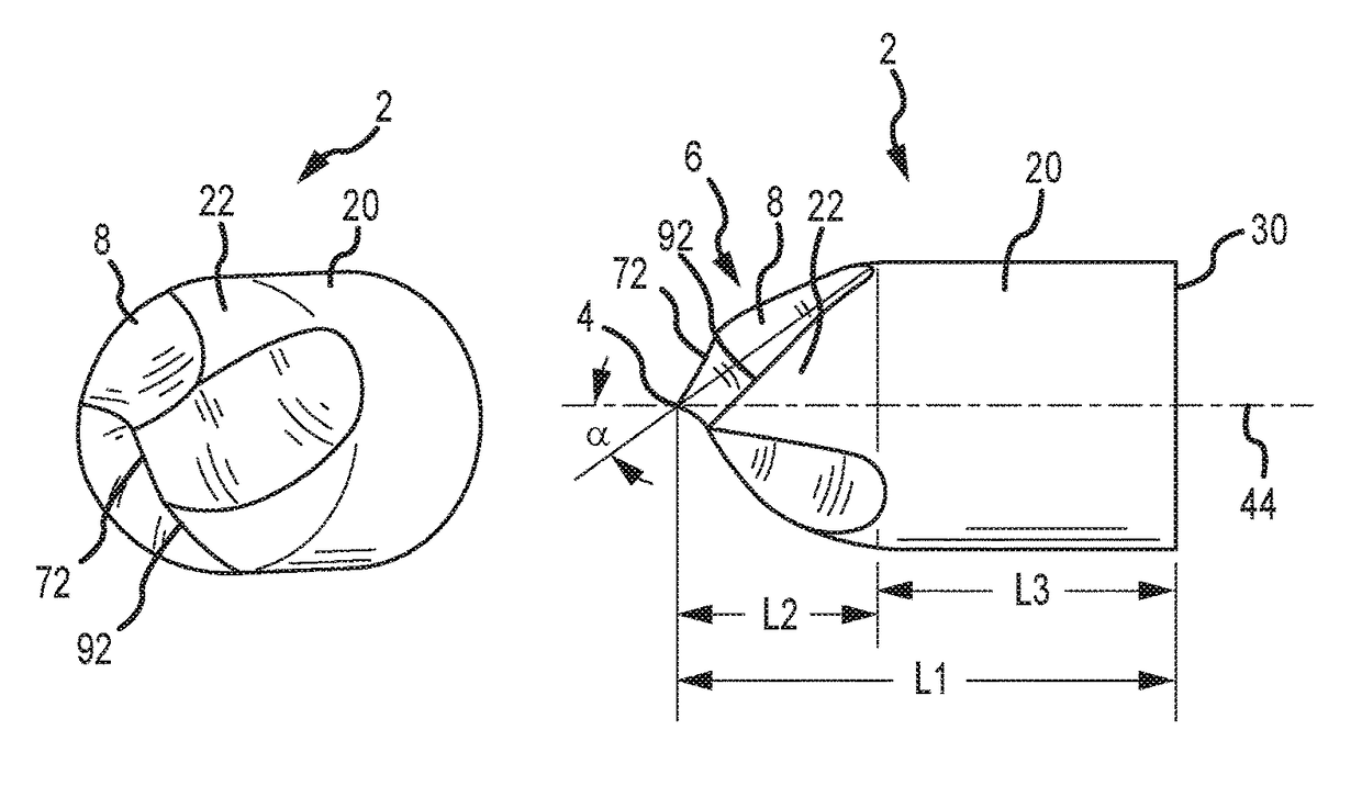
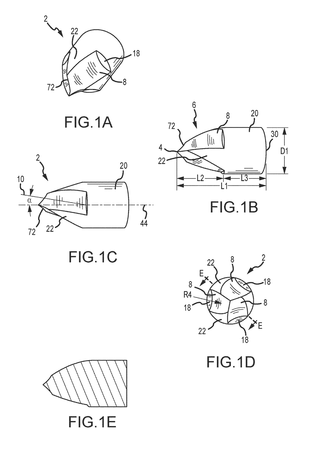
[0095]FIGS. 1A-E show a projectile 2 according to a FIG. 1A is a perspective view of the projectile 2. FIG. 1B is a side elevation view of the projectile 2. FIG. 1C is another side elevation view of the projectile 2. FIG. 1D is a top plan view of the projectile 2. FIG. 1E is a cross-sectional view of the projectile 2 taken along cut E-E of FIG. 1D. Note that FIGS. 1A-C are to scale.

[0096]The projectile 2 is for pistols and comprises a tip 4 on one end opposite a base 30 on the other end. The projectile 2 comprises a nose portion 6 and a cylindrical portion 20 (also called a shank). The nose portion 6 includes nose depressions 8 (also called cutouts or troughs) and nose remaining portions 22 (also called non-distorted portions or uncut portions) between two nose depressions 8. The remaining portions 22 are the uncut portions having the projectile's original ogive. The remaining portions 22 have a generally triangular shape with the tip of the triangle positioned proximate to the tip...

second embodiment

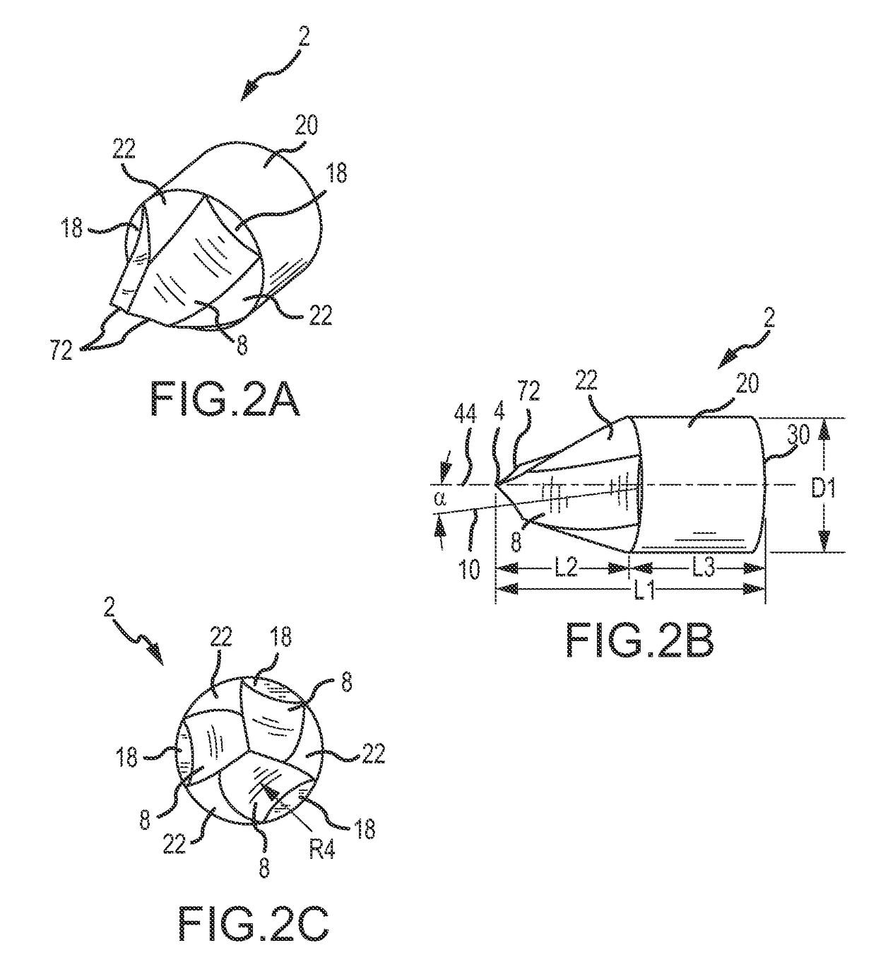
[0099]FIGS. 2A-C show a projectile according to the invention. This projectile is similar to the projectile of FIG. 1, except that this projectile 2 is two pieces: a nose portion 6 insert that is compression fit into a cylindrical portion 20 housing. Each piece may be a different material in one embodiment. For example, the nose portion 6 insert is made of steel and the cylindrical portion 20 housing is made of brass. However, the projectile 2 can be made of any projectile or bullet material, such as any metal alloy, brass, steel, tungsten, polymers, ceramics, aluminum, Inconel, or any other material known in the art. FIG. 2A is a perspective view of the projectile 2. FIG. 2B is a side elevation view of the projectile 2. FIG. 2C is a top plan view of the projectile 2. Note that FIGS. 2A-C are to scale.

[0100]The projectile 2 comprises a tip 4 on one end opposite a base 30 on the other end. The projectile 2 comprises a nose portion 6 and a cylindrical portion 20. The nose portion 6 in...

third embodiment

[0104]FIGS. 3A-E show a projectile 2 according to the invention. FIG. 3A is a perspective view of the projectile 2. FIG. 3B is a side elevation view of the projectile 2. FIG. 3C is a top plan view of the projectile 2. FIG. 3D is a cross section of the projectile 2 taken along cut D-D in FIG. 3C. FIG. 3E is an enlarged view of a portion of the projectile 2 shown in FIG. 3B. Note that FIGS. 3A-3D are to scale.

[0105]The projectile 2 comprises a tip 4 on one end opposite a base 30 on the other end. The projectile 2 comprises a nose portion 6 proximate the tip 4 on one end and interconnected to a cylindrical portion 20 on the other end. The cylindrical portion 20 is interconnected to a boat tail 38 on the end opposite the nose. The boat tail 38 terminates in the base 30 with a radius of curvature R8 between the boat tail 38 and the base 30. In alternate embodiments, the driving bands 26A vary in number, comprising one driving band 26A, a plurality of driving bands 26A, two driving bands ...


PUM


Abstract

The present invention provides a projectile device and a method of manufacture of a projectile device and in particular, to a pistol bullet and a rifle bullet and method of manufacture of same. In one embodiment, the projectile apparatus has a cylindrical body portion having a diameter, a front nose section tapering from a most proximal point of the projectile to the cylindrical body portion, and a rear tail section connected to the body portion and extending to the most distal point of the projectile, in which the front nose portion comprises a plurality of twisting depressions forming troughs.

Description

CROSS REFERENCE TO RELATED APPLICATIONS[0001]This application claims the benefit of priority from U.S. Provisional Patent Application Ser. No. 61 / 986,296, filed Apr. 30, 2014, entitled “Projectile with Enhanced Ballistics,” and U.S. Provisional Patent Application Ser. No. 62 / 145,814, filed Apr. 10, 2015, entitled “Projectile with Enhanced Ballistics,” the entire disclosures of which are hereby expressly incorporated by reference in their entireties.FIELD OF THE INVENTION[0002]Embodiments of the present invention are generally related to a projectile device and a method of manufacture of the same and in particular to a pistol bullet and a rifle bullet and method of manufacture of the same.BACKGROUND OF THE INVENTION[0003]Conventional projectiles, such as bullets, typically comprise a smooth uniform shank or body portion and an axially-symmetrical front or nose portion. Bullet performance is traditionally assessed with respect to parameters including velocity, ballistic coefficient (B...

Claims


Application Information

Patent Timeline
Patent Type & Authority Patents(United States)
IPC IPC(8): F42B12/02F42B10/24F42B10/26F42B10/46F42B12/06F42B12/74F42B10/22
CPCF42B12/02F42B10/22F42B10/24F42B10/26F42B10/46F42B12/06F42B12/74F42B30/02F42B12/34F42B5/025
Inventor MAHNKE, JOSHUA
Owner G9 HLDG LLC
Why Eureka
Try Eureka