Methods of high temperature infiltration of drill bits and infiltrating binder

a technology of drill bits and binder, which is applied in the field of infiltration of metal matrices with metal or metal alloy binders, can solve the problems of affecting the quality of drill bits, and requiring a long time period, so as to facilitate infiltration over a short period of time, increase strength, and melt relatively quickly

Inactive Publication Date: 2001-04-24
BAKER HUGHES INC
View PDF34 Cites 209 Cited by
  • Summary
  • Abstract
  • Description
  • Claims
  • Application Information

AI Technical Summary

Benefits of technology

In order to effect infiltration of the matrix with the inventive binder, the binder is melted by placing same into a furnace or an induction coil, or otherwise is heated, as known in the art. Preferably, the binder is melted relatively quickly in order to facilitate infiltration over a short period of time relative to that required by many conventional infiltration processes. Accordingly, an induction coil, or induction furnace, may be employed to melt the binder. The molten binder is then imbibed into the porous matrix by gravity, by capillary action, or under differential pressure. The use of differential pressure facilitates substantially complete infiltration of the matrix by the binder, and results in a bit body that is substantially free of voids or vugs.
Following infiltration of the matrix, the bit body is cooled. As the binder cools, it binds to the matrix particles in a manner which imparts the infiltrated matrix with increased strength over that of conventional copper alloy-infiltrated matrices. Preferably, cooling is conducted in a controlled, directional fashion in order to avoid the formation of stress gradients through the infiltrated matrix, which may occur if the bit body is permitted to cool inwardly from its periphery, as explained above. Cooling of the bit body may be effected by a computer-controlled system that monitors the temperatures at various positions of the infiltrated matrix and adjusts the areas of the bit body that are being cooled and heated to effect a desired cooling pattern.

Problems solved by technology

The use of conventional furnaces is, however, somewhat undesirable from the standpoint that a relatively long period of time is typically required when radiated heat is employed to heat the funnel, mold and binder to a temperature that is sufficient to effect infiltration of the porous matrix.
Thus, even after the surfaces of the infiltrated bit body matrix have cooled, a pool of molten binder may remain in the center of the bit body, which may generate stress gradients, such as shrinkage porosity or cracks, through the infiltrated matrix, which will likely weaken or damage the bit body.
Copper and the copper alloys that are typically employed to infiltrate drill bits are relatively low strength, low-toughness materials.
Copper alloy-infiltrated tungsten carbide bit bodies can also crack upon being subjected to the impact forces that are typically encountered during drilling.
Additionally, thermal stresses from the heat generated during fabrication of the bit or during drilling may cause cracks to form in the bit body.
Typically, such cracks occur where the cutting elements have been secured to the matrix body.
If the cutting elements are sheared from the drill bit body, the expensive diamonds on the cutter element are lost, and the bit may cease to drill.
As is known to those in the art, however, cobalt and iron, when molten, may dissolve, or "attack," carbon.
Thus, during infiltration of the porous matrix with binders which include significant amounts of these metals, the graphite funnels and molds that are typically employed in the infiltration of tungsten carbide bit bodies may be attacked and destroyed by cobalt, iron, or metal alloys which include these metals during exposure thereto.
Increased amounts of damage to the funnel and mold may occur with prolonged exposure to binders which include cobalt or iron.
Such damage to the graphite mold may result in an undesirably shaped bit body.
Consequently, the product yield of bit bodies that include cobalt- or iron-based alloy binders and that are infiltrated in graphite molds may be low, or the bit bodies may require further processing, such as machining, to remove excess material from the bit face.
Lower product yields and additional processing both increase manufacturing costs.
Nevertheless, HBN does not completely prevent metals such as cobalt and iron from attacking the graphite.
Thus, the use of HBN may not significantly increase product yields or significantly decrease manufacturing costs.

Method used


Image

  • Methods of high temperature infiltration of drill bits and infiltrating binder
  • Methods of high temperature infiltration of drill bits and infiltrating binder
  • Methods of high temperature infiltration of drill bits and infiltrating binder

Examples


Embodiment Construction

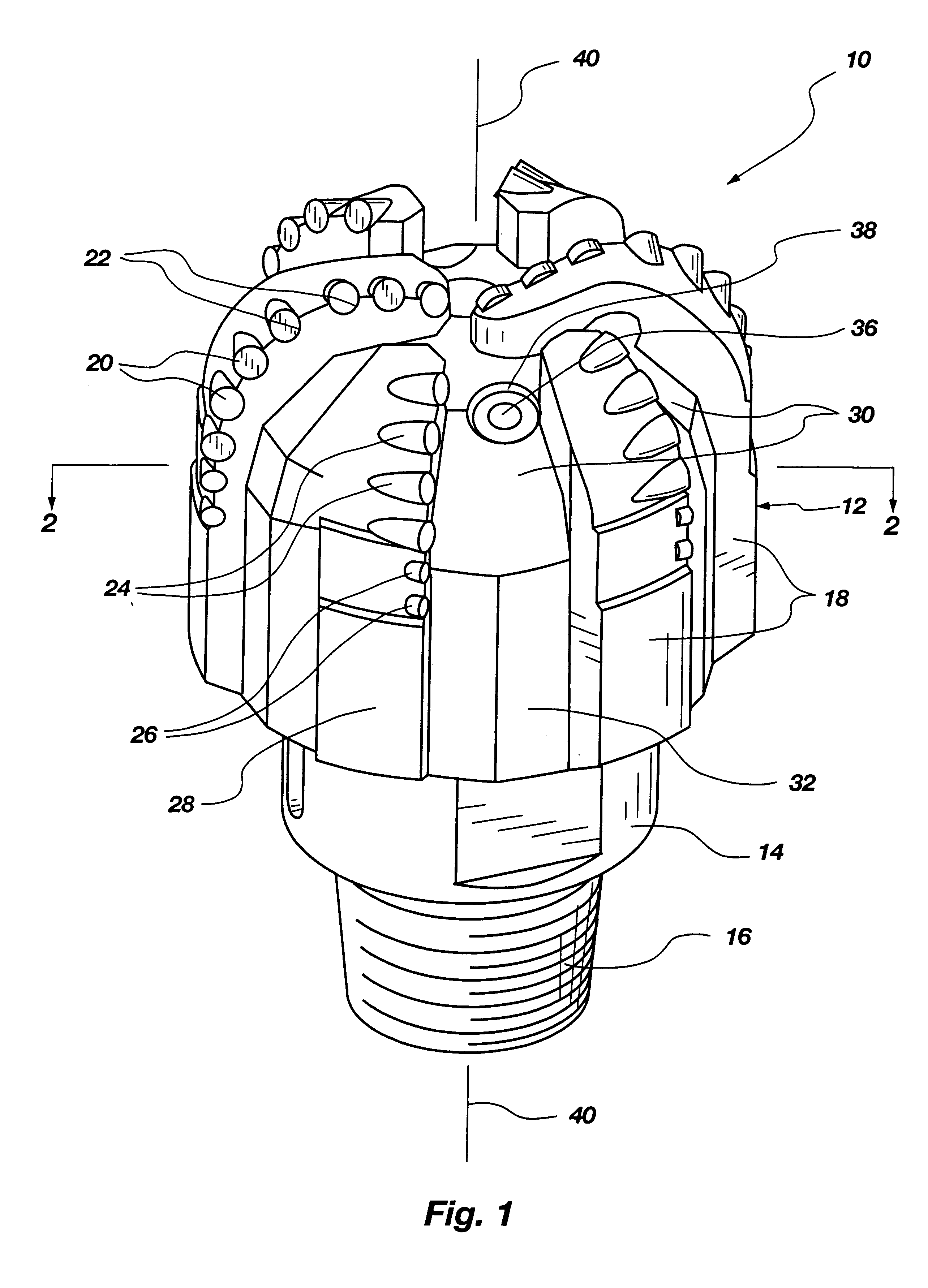
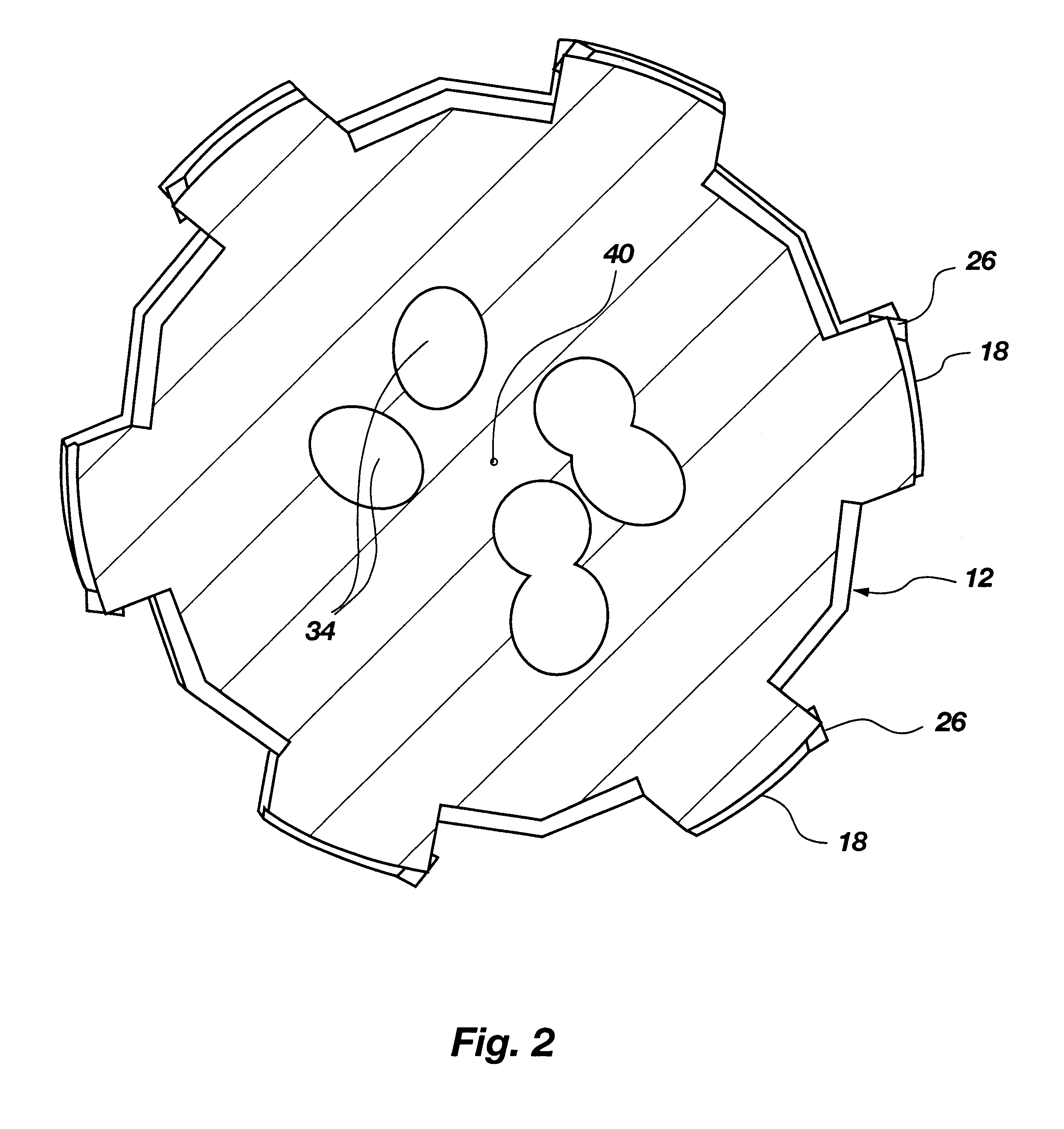
FIGS. 1 and 2 illustrate an exemplary drill bit 10 that may include the inventive infiltrating binder and which may be manufactured in accordance with the inventive process. Drill bit 10, as shown, includes a variety of external and internal components, such as a bit body 12 that includes six blades or wings 18 and gage pads 28 at the periphery of the bit body. Blades 18 are separated by generally radially extending fluid courses 30, which are continuous with junk slots 32 positioned between gage pads 28. Fluid courses 30 are continuous with internal fluid passages 34.

In operation, junk slots 32 are provided with drilling fluid, or "mud," from the drill string through shank 14, which communicates with internal fluid passages 34. The "mud" exits internal fluid passages 34 through nozzles 36, which are disposed in cavities 38 defined in fluid courses 30, and is directed along the fluid courses to junk slots 32.

At the distal end of the bit body 12, blades 18 include sockets 22 with inc...


PUM

PropertyMeasurementUnit
melting temperaturesaaaaaaaaaa
melting temperatureaaaaaaaaaa

Abstract

A method of manufacturing a bit body, other drilling-related component, or other article of manufacture, including fabricating a particulate-based matrix and infiltrating the particulate-based matrix with a binder that includes cobalt or iron. The binder may be a cobalt alloy or an iron alloy. The particulate-based matrix may be disposed within a non-graphite mold. The particulate-based matrix and binder are placed within an induction coil and an alternating current is applied to the induction coil in order to directly heat the binder, permitting the binder to infiltrate or otherwise bind the particles of the matrix together. The molten binder may then be directionally cooled by forming a cooling zone around an end portion of the bit body and increasing the size of the cooling zone relative to the bit body. The invention also includes a bit body, other drilling-related component, or other article of manufacture which includes a particulate-based matrix that is bound together with a binder that includes iron or cobalt.

Description

BACKGROUND OF THE INVENTION1. Field of the InventionThe present invention relates to processes for infiltrating metal matrices with a binder. In particular, the present invention relates to processes for infiltrating tungsten carbide matrices with metal or metal alloy binders. More specifically, the present invention relates to processes for manufacturing earth boring drill bits which include infiltrating a tungsten carbide matrix with a high-strength metal or metal alloy binder.2. Background of Related ArtConventionally, earth boring drill bits that include a powdered or particulate refractory material matrix, which are also referred to as particulate-based drill bits, have been manufactured by processes such as sintering and infiltration. Conventional infiltration techniques typically include the formation of a somewhat porous matrix of powdered or particulate material and the infiltration thereof by powder metallurgy processes. U.S. Pat. No. 3,757,878, which issued to Wilder et a...

Claims


Application Information

Patent Timeline
Patent Type & Authority Patents(United States)
IPC IPC(8): B22D19/14B22D19/06C22C1/10E21B10/46
CPCB22D19/06B22D19/14C22C1/1015C22C1/1036E21B10/46B22F3/105B22F3/1028B22F2005/001B22F2999/00
Inventor BUTCHER, TRENT N.
Owner BAKER HUGHES INC
Why Eureka
Try Eureka