Selectively cooled or heated cushion and apparatus therefor

a technology which is applied in the field of selectively cooled or heated cushions and apparatus therefor, and can solve the problems of less power available for air conditioning or heating equipment, less discomfort for vehicle occupants, and ineffectiveness of all other substitute materials known for this purpose,

Inactive Publication Date: 2000-07-11
FEHER STEVE
View PDF20 Cites 207 Cited by
  • Summary
  • Abstract
  • Description
  • Claims
  • Application Information

AI Technical Summary

Problems solved by technology

In warm seasons, these same vehicles which have conventional air conditioning systems that direct cool air directly on the front of passengers and into the vehicle interior generally, undesirably leave those portions of the individual directly facing and contacting the seat and backrest cushions at an undesirably elevated temperature and, in the case of high humidity, this results in even more discomfort for the vehicle occupant.
At the present time, all other substitute materials known for this purpose do not possess the same high level of efficiency and are, in truth, substantially inferior in normal operation to those being eliminated.
Also, there is the increasing problem that future automotive vehicles may be required to operate on less and less power in order to conserve basic fuels as well as reduce harmful byproducts, and this will, of necessity, leave a lesser proportion of available power for use by air conditioning or heating equipment.
Still further, automotive seat manufacturer's consider it undesirable that internal supports (e.g., spring coils) should produce a visible surface impression and in that way destroy design esthetics.
It has been found in this regard to be self defeating to merely increase the thickness of a comfort layer located over wire springs or rigid plastic tubes since this reduces heat transference and thus overall operational efficiency.

Method used


Image

  • Selectively cooled or heated cushion and apparatus therefor
  • Selectively cooled or heated cushion and apparatus therefor
  • Selectively cooled or heated cushion and apparatus therefor

Examples


Embodiment Construction

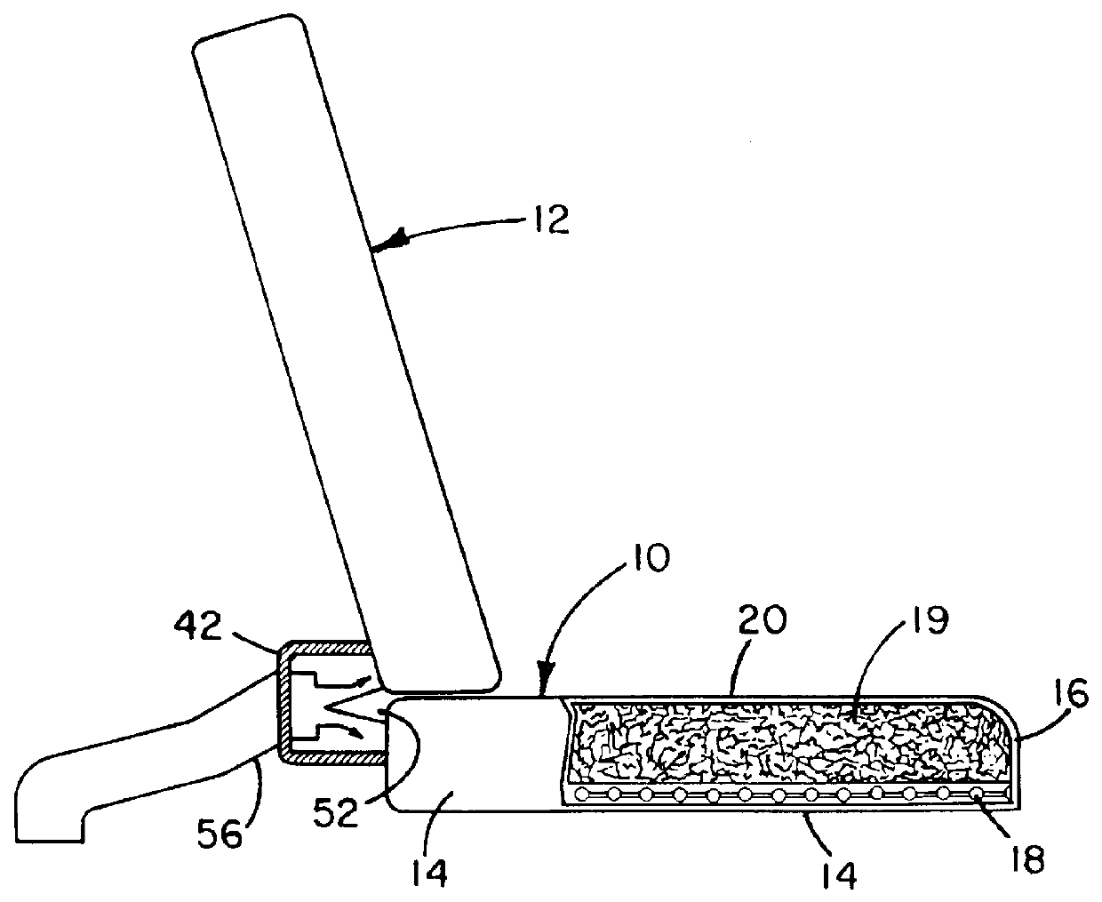
Turning now to the drawings and particularly FIG. 1, the invention is shown and described in connection with a pair of cushions 10 and 12 which are manufactured in accordance with the principles of the invention and are particularly adaptable for use in an automotive vehicle where the cushion 10 comprises a seat and the cushion 12 is a backrest. Construction of the two cushions 10 and 12 is identical, therefore, only the construction of cushion 10 will be given in detail.

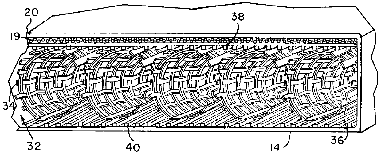
With additional reference to FIG. 2, cushion 10 is seen to include an outer lower layer 14 covering the cushion bottom, two lateral sides and rear side which can be made of any of a number of different materials with the primary physical characteristic being that it is impermeable to the passage of air and moisture therethrough. An internal portion 16 to be more particularly described later forms a plenum for receiving temperature conditioned air and at the same time providing comfort and possessing necessary rigidi...


PUM


Abstract

A cushion (10, 12) has a plenum (16) which includes a plurality of flexible plastic woven tubes (34) held within a pair of similarly woven sheathes (38,40). The plenum has its sides and bottom covered by an air impermeable (14) layer with the top covered by an air permeable layer (20). A low to medium density foam pad (19) is located between the plenum (16) and the top layer (20). Conditioned air is provided to the cushions (10,12) from a Stirling cycle heat pump (44).

Description

1. Field of the InventionThe present invention relates to a cushion, such as for use as a mattress or seat and backrest, for example, which presents an outer surface of selectively variable temperature and apparatus therefor including a heat pump for reducing cushion temperature operating on a Stirling cycle.2. Description of Related ArtThere are many situations in which it is desirable that a cushion, such as a seat and backrest in an automotive vehicle, for example, be capable of being selectively cooled or heated for the comfort of someone sitting or resting against the cushion. In the colder climates, it would be desirable, particularly in the winter time, to obtain relatively instant heating of the seat cushions to warm an individual sitting or leaning on them prior to normal actuation of the auto heating system which typically relies upon the engine coolant being brought up to a sufficiently high temperature for satisfactory operation. In warm seasons, these same vehicles whic...

Claims


Application Information

Patent Timeline
Patent Type & Authority Patents(United States)
IPC IPC(8): A47C7/74A47C7/72A47C27/22
CPCA47C7/74A47C27/22
Inventor FEHER, STEVE
Owner FEHER STEVE
Why Eureka
Try Eureka