
Cable signal detector

a signal detector and cable technology, applied in the direction of instruments, data switching networks, indicating the presence of current/voltage, etc., can solve the problems of inability to identify whether or not communication is actually performed using the communication cable, inability to identify the presence or absence of information communication, and the communication cable is likely to be erroneously unplugged, so as to suppress the erroneous unplugging of the communication cable and suppress the degradation of the signal

Active Publication Date: 2017-07-18
HITACHI METALS LTD
View PDF8 Cites 0 Cited by
  • Summary
  • Abstract
  • Description
  • Claims
  • Application Information

AI Technical Summary

Benefits of technology

The present invention provides a cable signal detector that can display the presence or absence of information communication. This helps to prevent incorrect unplugging of communication cables, use of general-purpose cables, and degradation of signals during transmission. Overall, the invention helps to improve the reliability and efficiency of cable communication systems.

Problems solved by technology

However, the conventional art as described above has the problem that it is only able to identify whether or not the communication cables are being physically connected, but unable to identify whether or not communication is actually performed using the communication cables, in other words, unable to identify the presence or absence of information communication.
For this reason, with the presence of communication being unidentified, the communication cables are likely to be erroneously unplugged, and it is also conceivable that a failure such as an information communication equipment service outage, transfer data corruption, or the like occurs.
Moreover, there is also the problem that when the connections of the communication cables are monitored as in Japanese Patent No. 5,274,671, because the communication cables are required to be equipped with a built-in monitoring signal line, no general-purpose communication cable can be used, and cost becomes high.

Method used


Image

  • Cable signal detector
  • Cable signal detector

Examples


Embodiment Construction

[0029]Below is described an embodiment according to the invention, in conjunction with the accompanying drawings.

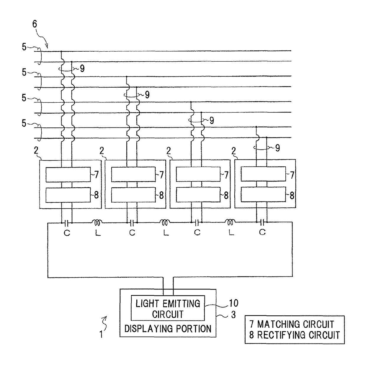
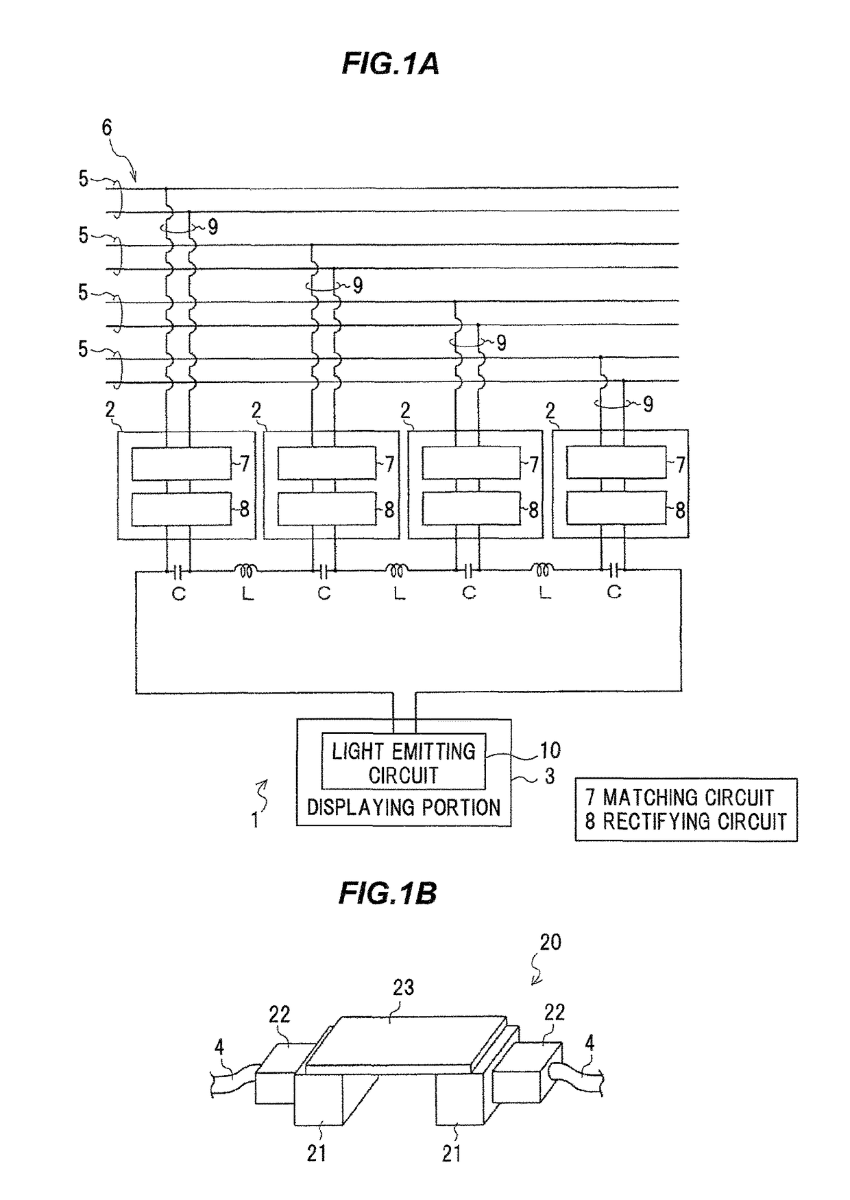
[0030]FIG. 1A is a schematic configuration diagram showing a cable signal detector 1 in the present embodiment, and FIG. 1B is a perspective view showing a relay connector for the cable signal detector 1 to be mounted thereon.

[0031]As shown in FIGS. 1A and 1B, the cable signal detector 1 is configured to detect the presence or absence of information communication in a communication cable 4 including a plurality of signal line pairs (not shown) for differential signaling, and is equipped with a plurality of detecting portions 2 and a displaying portion 3.

[0032]As the communication cable 4, it is possible to use a general-purpose LAN (Local Area Network) cable. This embodiment uses the communication cable 4 including four signal line pairs (eight signal lines in total) for differential signaling.

[0033]The plurality of detecting portions 2 and the display portion 3 are provi...


PUM


Abstract

A cable signal detector is configured to detect the presence or absence of information communication in a communication cable including a plurality of signal line pairs for differential signaling. The cable signal detector includes a plurality of detecting portions each of which is configured to partially branch and draw a transmission signal from a different signal line pair, rectify the branched and drawn signal into a direct current, and output that direct current, and a displaying portion configured to display the presence or absence of information communication, based on outputs of the plurality of detecting portions. The outputs of the plurality of detecting portions are connected in series, and the displaying portion is configured to display the presence or absence of information communication, based on an overall output voltage of the plurality of detecting portions connected in series.

Description

[0001]The present application is based on Japanese patent application No. 2014-228958 filed on Nov. 11, 2014, the entire contents of which are incorporated herein by reference.BACKGROUND OF THE INVENTION[0002]1. Field of the Invention[0003]This invention relates to a cable signal detector.[0004]2. Description of the Related Art[0005]In data centers and the like, a layout change, movement, or addition of information communication equipment such as servers, hubs, etc. requires a change of connections of communication cables, such as LAN (Local Area Network) cables, etc.[0006]To determine the presence or absence of connections of the communication cables, some information communication equipment has a lamp for identifying connections of the communication cables.[0007]Also, an information communication equipment has also been proposed that detects connector insertion or removal for the communication cables, to monitor connections of the communication cables (See e.g. Japanese Patent No....

Claims


Application Information

Patent Timeline
Patent Type & Authority Patents(United States)
IPC IPC(8): G08B21/00H04L29/06H04B10/07H04L12/413G01R19/145
CPCH04L29/06H04B10/07H04L12/413G01R19/145H04L9/40
Inventor SHIRAKAWA, YOHEIHIRANO, KOKIAGEISHI, YOSHITAKE
Owner HITACHI METALS LTD
Learn More