

electronic components
A technology of electronic components and components, applied in electrical components, transformer/inductor components, circuits, etc., can solve the problems of weakened coupling and deterioration of signal transmission characteristics, so as to suppress the degradation of signal quality, reduce deterioration, and enhance coupling Effect
- Summary
- Abstract
- Description
- Claims
- Application Information
AI Technical Summary
Problems solved by technology
Method used
Image

Examples
no. 1 approach
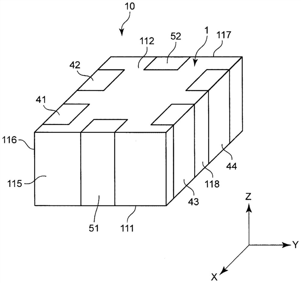
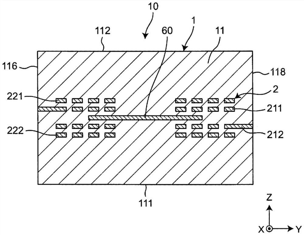
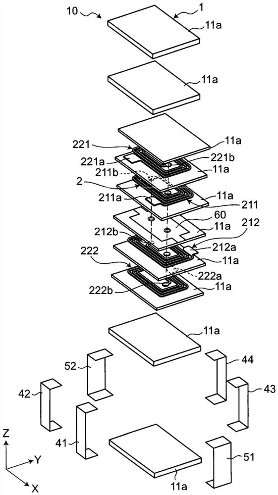
[0060] figure 1 It is a perspective view which shows the electronic component which concerns on 1st Embodiment of this invention. figure 2 is a cross-sectional view of an electronic component. image 3 It is an exploded perspective view of an electronic part. Such as figure 1 , figure 2 , image 3 As shown, the electronic component 10 has: a laminated body 1, a common mode choke coil 2 provided in the laminated body 1, an inner ground electrode 60 provided in the laminated body 1, and a first ground terminal 51 connected to the inner ground electrode 60 , the second ground terminal 52 .
[0061] The electronic component 10 is electrically connected to the mounting substrate. The electronic component 10 is mounted, for example, in electronic equipment such as a personal computer, a DVD player, a digital camera, a TV, a mobile phone, and an electric vehicle.
[0062] The laminated body 1 includes a plurality of laminated insulating layers. Specifically, the laminated...
no. 2 approach
[0093] Figure 5 It is a YZ cross-sectional view showing the second embodiment of the electronic component of the present invention. The second embodiment differs from the first embodiment in the structure in which the outer ground electrode is provided. Hereinafter, this different configuration will be described. In addition, in the second embodiment, the same reference numerals as those in the first embodiment denote the same configurations as in the first embodiment, and thus descriptions thereof are omitted.
[0094] Such as Figure 5 As shown, in the electronic component 10A of the second embodiment, one of the second coils 221 is disposed at the uppermost position in the stacking direction of the first coil 211 to the second coil 222, and the second coil 221 is placed outside the stacking direction ( The upper side) is provided with an outer ground electrode 61 facing the second coil 221 . The outer ground electrode 61 is arranged inside the laminated body 1 (nonmagn...
no. 3 approach
[0101] Figure 7 It is a YZ cross-sectional view showing the third embodiment of the electronic component of the present invention. The third embodiment differs from the first embodiment in the structure in which the outer ground electrodes are provided. Hereinafter, this different configuration will be described. In addition, in the third embodiment, the same reference numerals as those in the first embodiment denote the same configurations as in the first embodiment, and thus descriptions thereof are omitted.
[0102] Such as Figure 7 As shown, in the electronic component 10B of the third embodiment, the second coils 221 and 222 are arranged at the uppermost and lowermost positions in the stacking direction of the first coil 211 to the second coil 222 . A first outer ground electrode 61 facing the second coil 221 is provided on the outer side (upper side) of the one second coil 221 in the stacking direction. A second outer ground electrode 62 facing the second coil 222 ...
PUM
 Abstract
Description
Claims
Application Information