Liquid crystal display device and backlight thereof

a liquid crystal display and backlight technology, applied in the direction of lighting and heating apparatus, instruments, mechanical apparatus, etc., to achieve the effect of preventing the generation of bright lines and/or black lines, preventing the deterioration of liquid crystal generated, and preventing the generation of wrinkles

Inactive Publication Date: 2006-08-01
LG DISPLAY CO LTD
View PDF5 Cites 46 Cited by
  • Summary
  • Abstract
  • Description
  • Claims
  • Application Information

AI Technical Summary

Benefits of technology

[0013]In order to overcome the problems according to the conventional art, the present invention provides an LCD device including a backlight thereof in which the generation of a bright line and / or a black line is prevented, the deterioration of the liquid crystal generated is prevented, and the generation of wrinkles is prevented on a sheet reflector.

Problems solved by technology

First, after the construction, the edge of light guide 3 is placed between both upper and lower extensions of the lamp housing 9. To prevent wrinkles on the sheet reflector 2 with this construction, a gap must occur between the upper surface of the light guide 3 and the lower surface of the upper end of the lamp housing 9.
Unfortunately, if the print density is too great, then a black line is generated, and if the print density is too slight, then the bright line will still be generated.

Method used


Image

  • Liquid crystal display device and backlight thereof
  • Liquid crystal display device and backlight thereof
  • Liquid crystal display device and backlight thereof

Examples


first embodiment

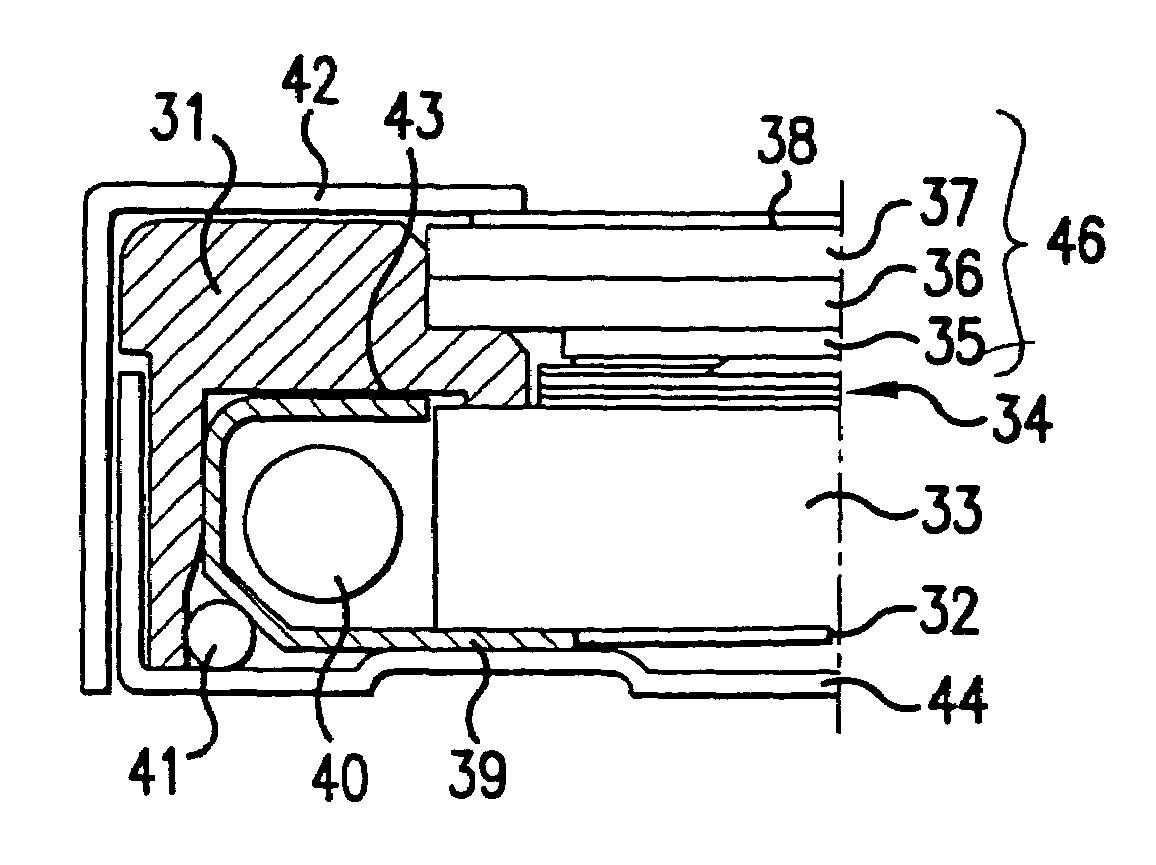
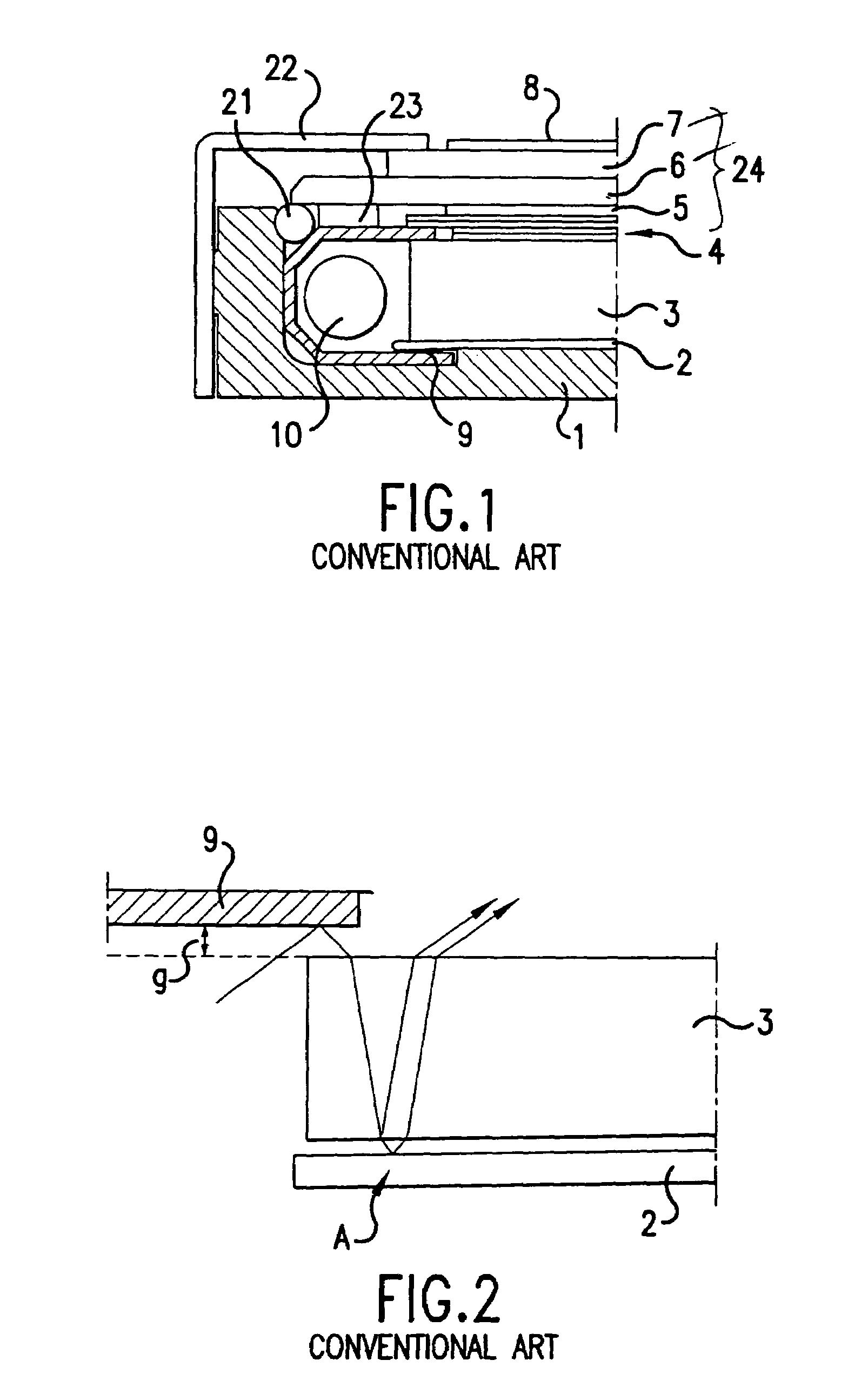
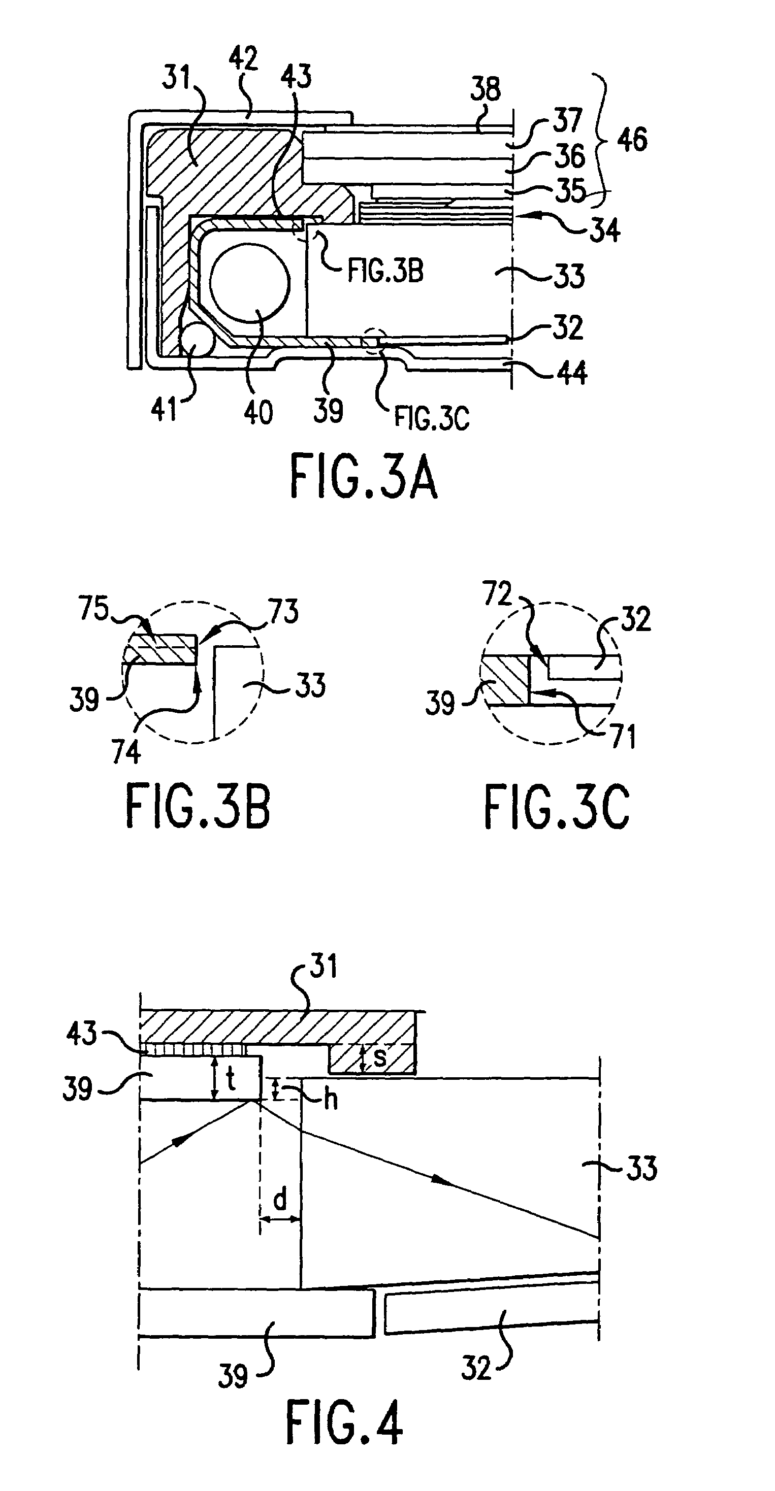
[0031]In the conventional art, as shown in FIG. 1, the end portion of the sheet reflector 2 is inserted between the lower surface of the light guide 3 and the lower extension of the lamp housing 9. But in the first embodiment, as shown in FIG. 3C, an end portion 72 of the sheet reflector 32 and the end portion 71 of the lower extension of the lamp housing 39 are apart from each other. As a result, the sheet reflector 32 is not pressed by the lamp housing 39, which prevents wrinkles from being generated on the sheet reflector 32.

[0032]Also as a shown in FIG. 1, the conventional LCD device has a portion of the upper extension of the lamp housing 9 extends over a portion of the upper surface of the light guide 3. In the first embodiment according to the present invention (as shown in more detail in FIG. 3B), however, at least a portion of the side edge 73 of the upper extension of the lamp housing 39 faces the side edge of the light guide 33. In other words, no vertical gap exists betw...

second embodiment

[0053]In the second embodiment, the end portion 83 of the upper extension of the lamp housing 59 does not face the side edge the light guide 33. That is, the upper extension of the lamp housing 59 is entirely above the upper surface of the light guide 33.

[0054]In this structure, the inner space of the lamp housing 59 is wider than the inner space of the lamp housing of the first embodiment. This in turn decreases the amount of light being absorbed after being reflected back into the lamp 40 is decreased, and increases the amount of light entering the side edge of the light guide 33 when compared to the first embodiment. More light incident to the side edge of the light guide 33 increases the brightness of the plane lamp.

[0055]Also as mentioned previously, because the light entering the gap is scattered or absorbed by the main supporter 31, the bright line is still considerably less when compared to the conventional art.

[0056]FIG. 8 is a view showing a third embodiment according to t...


PUM

PropertyMeasurementUnit
thicknessaaaaaaaaaa
heightaaaaaaaaaa
heightaaaaaaaaaa

Abstract

In a liquid crystal display device according to the present invention, an upper end portion of a lamp housing is fixed on a main supporter so that the lamp housing can be made to face a side edge of a light guide. Light that can cause bright lines is eliminated or minimized through absorption or scattering by a main supporter. The main supporter is also thermally insulating and is placed between the lamp housing and a liquid crystal panel. Further, a thermally conducting bottom cover is placed under the backlight. Therefore, heat generated from the lamp is effectively channeled away from the light guide to prevent liquid crystal panel deterioration. Still further, although the upper and lower surfaces of the light guide is tightly fit between the lamp housing and the main supporter, wrinkles on a sheet reflector are prevented because the sheet reflector is not stacked between the lamp housing and a lower surface of the light guide.

Description

CROSS-REFERENCES TO RELATED APPLICATIONS[0001]This application is a divisional of U.S. application Ser. No. 09 / 520,880 filed on Apr. 5, 2000 now issued as U.S. Pat. No. 6,690,435. This nonprovisional application claims priority under 35 U.S.C. § 119(a) on Patent Application No. 1999-15641 filed in Korea on Apr. 30, 1999. The entirety of each of the above-identified documents are hereby incorporated by reference.BACKGROUND OF THE INVENTION[0002]The present invention relates to a liquid crystal display device and a backlight thereof. More specifically, the present invention relates to preventing the deterioration of liquid crystal panel and preventing the generation of wrinkles on a sheet reflector while decreasing generations of a bright line and / or a black line.[0003]A liquid crystal display device (LCD) has been widely used as a display for notebook computers and portable TVs among others. An LCD fundamentally includes a liquid crystal panel and a backlight applying a lamp light to...

Claims


Application Information

Patent Timeline
Patent Type & Authority Patents(United States)
IPC IPC(8): F21V7/04G02F1/1335F21V8/00G02B6/00G02F1/13357
CPCG02B6/0031G02F1/133615G02B6/0088G02B6/0055G02F1/1335
Inventor HA, KYOUNG SUJANG, MYONG GI
Owner LG DISPLAY CO LTD
Why Eureka
Try Eureka