

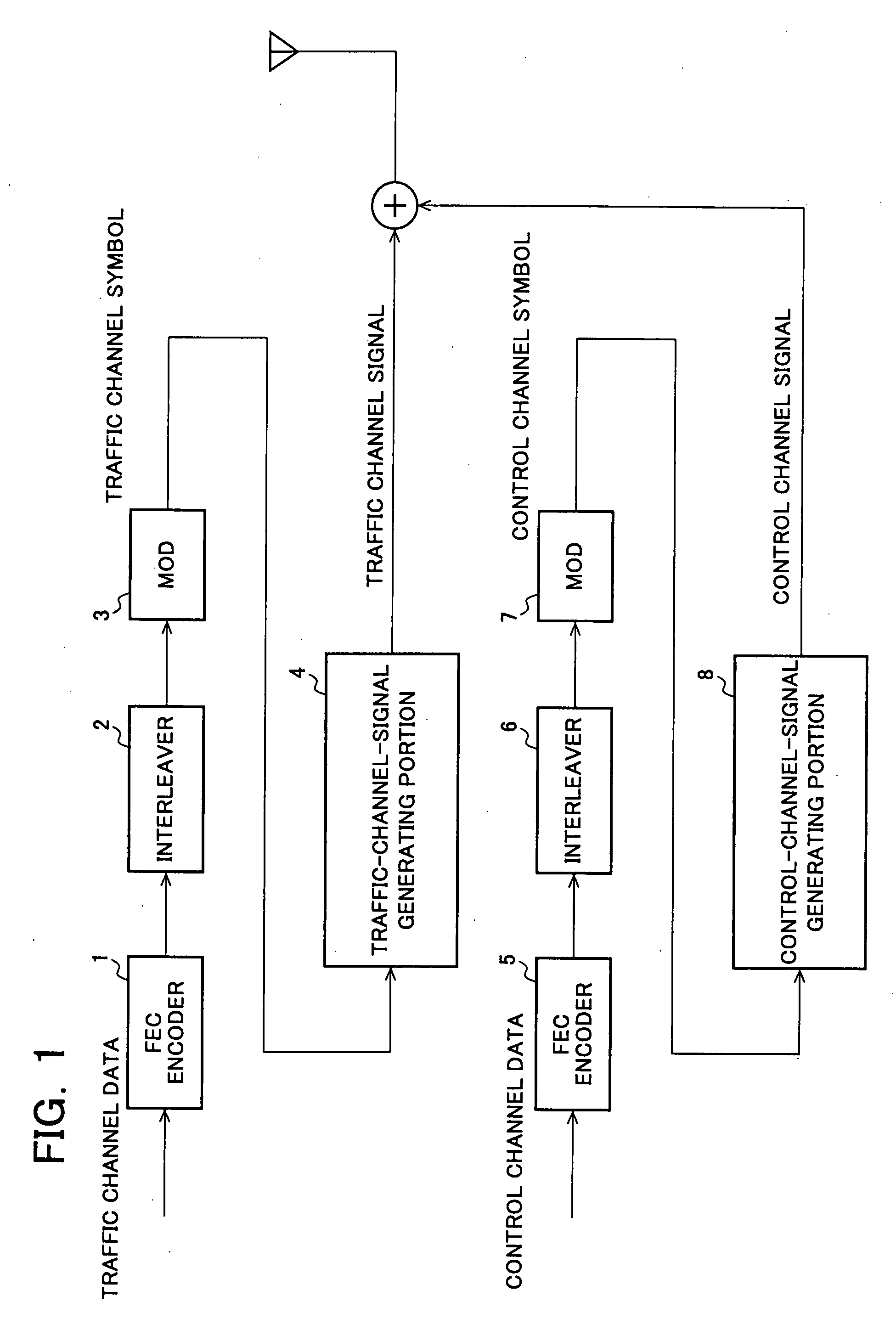
Receiver Apparatus and Transmitter Apparatus
a receiver and transmitter technology, applied in the field of data communication systems, receiver apparatuses, and transmitter apparatuses, can solve the problems of one-based technology and dm technology, and achieve the effect of minimizing the deterioration of the quality of the traffic channel, and reducing the transmission speed of the traffic channel
- Summary
- Abstract
- Description
- Claims
- Application Information
AI Technical Summary
Benefits of technology
Problems solved by technology
Method used
Image

Examples
sixth embodiment
[0154]FIG. 9 is a block diagram showing the configuration of a receiver according to a sixth embodiment of the present invention. It is assumed in the present embodiment that a signal transmitted from a transmitter as described in the first embodiment or the fourth embodiment is received through a wireless channel.
[0155] First, timing-detection / channel-estimation processing 11 performs timing detection and channel estimation to determine timing for extracting a reception signal for performing FFT processing and channel estimation values. From the channel estimation values, a weighting factor by which each subcarrier is to be multiplied after FFT processing is determined. Although a complex conjugate of a channel gain corresponding to frequency components of each subcarrier of the channel is used as the weighting factor, the method for determining the weighting factor is not limited thereto. The channel estimation values are also used when a control-channel-signal canceller portion ...
seventh embodiment
[0160] Although signals in a time domain are used for canceling in FIGS. 9 and 10, canceling can also be performed for each subcarrier in a frequency domain as shown in FIGS. 11 and 12. FIG. 11 is a block diagram showing the configuration of a receiver according to a seventh embodiment of the present invention.
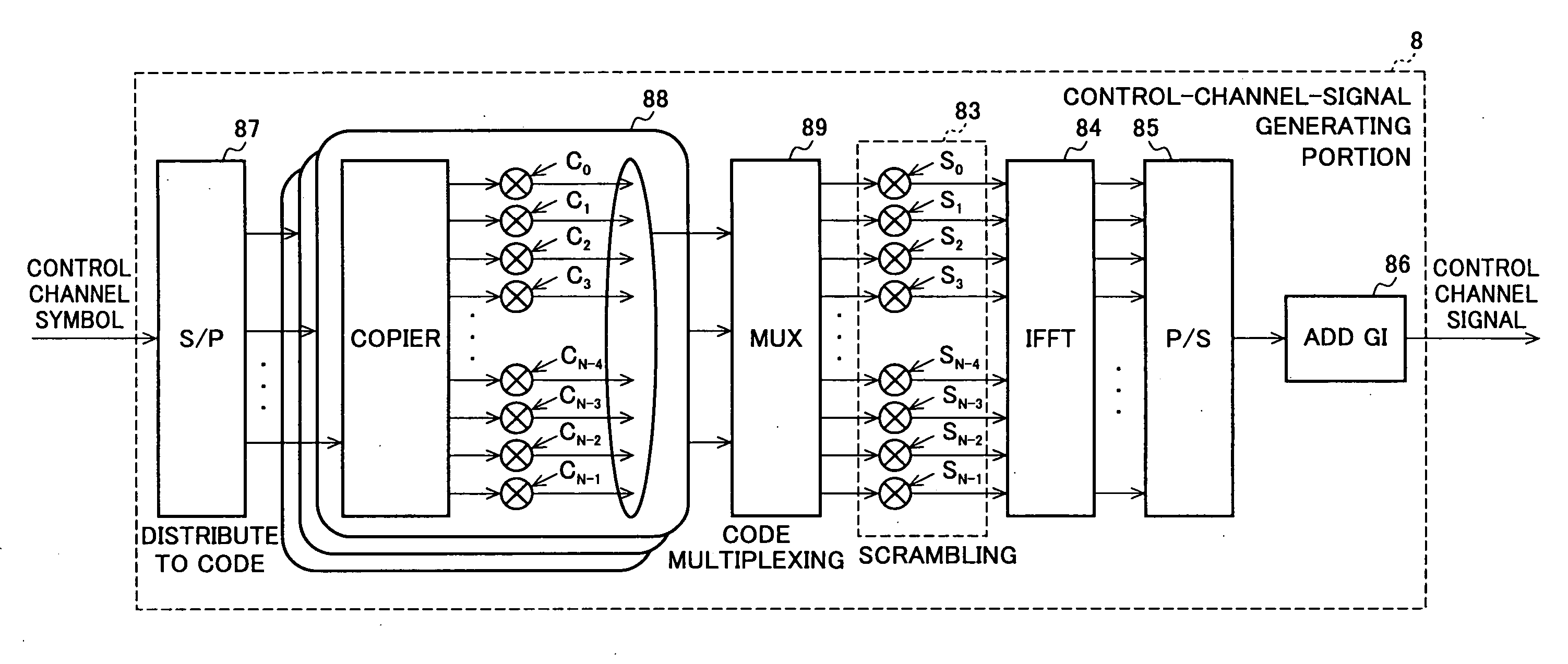
[0161] In the seventh embodiment, a reception signal from which a guard interval was removed by a Remove GI 12 is subjected to despreading processing 15. In this case, the reception signal is subjected to S / P conversion 151 and is subjected to FFT processing 152 to be converted into subcarrier components. Signals at a point of time when descrambling 153 is performed are stored in a memory 13. The control channel signals are directly subjected to frequency-domain despreading processing 154 and P / S conversion 155 and are then subjected to symbol determination (Decision 19). A control-channel-signal canceller portion 14 cancels a control cannel signal in a frequency domain. P / S ...
eighth embodiment
[0163]FIG. 13 is a block diagram showing the configuration of a receiver according to an eighth embodiment of the present invention. First, timing-detection / channel-estimation processing 11 performs timing detection and channel estimation to determine timing for extracting a reception signal for performing FFT processing and channel estimation values. From the channel estimation values, a weighting factor by which each subcarrier is to be multiplied after FFT is determined.
[0164] A guard interval of the reception signal is removed by a Remove GI 12, the resulting signal is temporarily stored in a memory 13, and the control channel is first demodulated. Since the control channel has been subjected to OFCDM modulation involving frequency domain spreading, the complex conjugates of the spreading code used for the spreading and the weighting factors determined by the timing-detection / channel-estimation processing 11 are used to perform despreading processing 15. In this case, S / P conve...
PUM
 Abstract
Description
Claims
Application Information