Transmitting method, receiving method, transmitting device, receiving device and tranceiving device

a technology of transmitting method and receiving device, applied in the field of transmitting device, can solve the problems of insufficient measures against changes in the state of the communication path, difficult adaptive measures to be performed, etc., and achieve the effect of reducing transmission speed and high-quality data transmission

Inactive Publication Date: 2007-06-28
PANASONIC CORP
View PDF10 Cites 16 Cited by
  • Summary
  • Abstract
  • Description
  • Claims
  • Application Information

AI Technical Summary

Benefits of technology

[0013] An object of the present invention is to provide a transmitting device and a receiving device for an ultra wideband communication system and an art related thereto, the transmitting and receiving devices being able to perform high-quality data transmission without reducing transmission speed, by lifting the restriction over the number of repetitive pulses in the UWB-IR method and by posing weighting on the encoded bits.

Problems solved by technology

That is, the conventional technology mentioned above does not take into consideration changing in the significance of the encoded bits adaptively in consideration of the state of the communication path; hence, measures against changes of the state of the communication path are insufficient.
Accordingly, adaptive measures are difficult to be performed, by allotting many repetitive pulses to an encoded bit which is susceptible to adverse effect by noises and interference from other users, or by allotting, on the other hand, less repetitive pulses to an encoded bit which is hard to be influenced by the adverse effect.

Method used


Image

  • Transmitting method, receiving method, transmitting device, receiving device and tranceiving device
  • Transmitting method, receiving method, transmitting device, receiving device and tranceiving device
  • Transmitting method, receiving method, transmitting device, receiving device and tranceiving device

Examples


embodiment 1

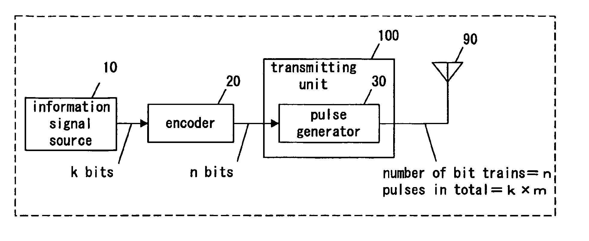
[0070]FIG. 1 is a block diagram of a transmitting device according to Embodiment 1 of the present invention. As shown in FIG. 1, the transmitting device of the UWB-IR method of the present embodiment comprises an encoder 20, a transmitting unit 100, and an antenna 90. The transmitting unit 100 includes a pulse generator 30.

[0071] Hereinafter, operation of the transmitting device of the present embodiment is explained. A k-bit information bit train inputted from an information signal source 10 is encoded to an n-bit encoded bit train with a coded rate (k / n) by the encoder 20 (“k” is a natural number not less than “1”, and “n” is a natural number not less than “2”). The n-bit encoded bit train is inputted into the pulse generator 30 of the transmitting unit 100. In the pulse generator 30, a series of tens of pulses to hundreds of pulses each having a short duration are generated repetitively per each bit of the n-bit encoded bit train, and the pulses are transmitted from the antenna ...

embodiment 2

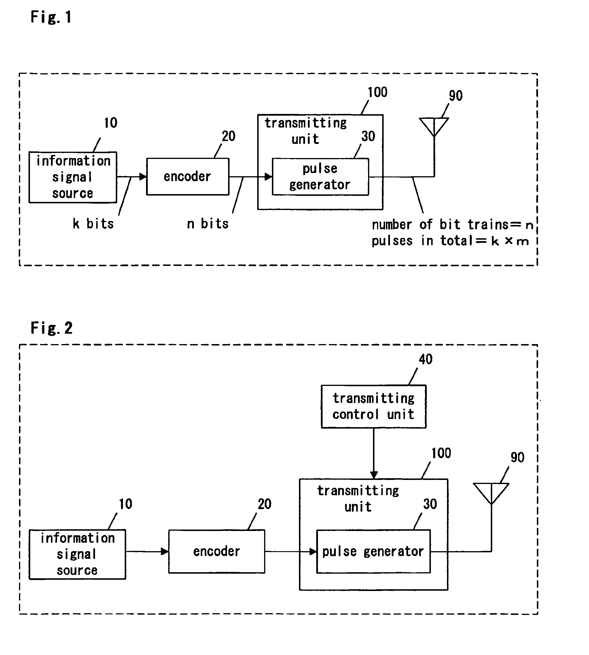
[0080]FIG. 2 is a block diagram of a transmitting device according to Embodiment 2 of the present invention. In FIG. 2, description is omitted by giving the same symbols regarding the same components as in FIG. 1.

[0081] The transmitting device of the present embodiment as shown in FIG. 2 comprises an encoder 20, a transmitting unit 100, a transmitting control unit 40 and an antenna 90. The transmitting unit 100 includes a pulse generator 30. Compared with the transmitting device of Embodiment 1 of the present invention as shown in FIG. 1, the transmitting device of the present embodiment additionally comprises the transmitting control unit 40 operable to control the pulse generator 30.

[0082] The transmitting control unit 40 acquires communication path information transmitted from a receiving device, the information indicating a communication state of a communication path. The transmitting control unit 40 generates control information for controlling the pulse generator 30 based on...

embodiment 3

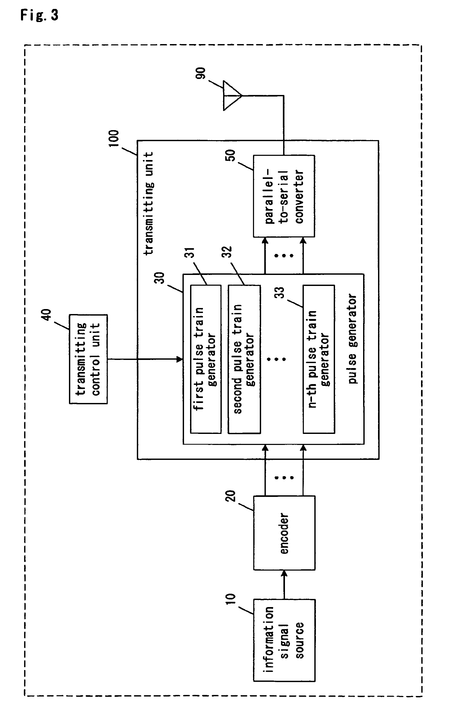
[0086]FIG. 3 is a block diagram of a transmitting device according to Embodiment 3 of the present invention. In FIG. 3, explanation of components same as shown in FIG. 1 is omitted attaching same symbols as in FIG. 1.

[0087] The transmitting device of the present embodiment shown in FIG. 3 comprises an encoder 20, a transmitting unit 100, a transmitting control unit 40, and an antenna 90. The transmitting unit 100 comprises a pulse generator 30 and a parallel-to-serial converter 50. Furthermore, the pulse generator 30 comprises a first pulse train generator 31, a second pulse train generator 32, and an n-th pulse train generator 33.

[0088] A k-bit information bit train is inputted from an information signal source 10. The encoder 20 encodes the k-bit information bit train to an n-bit encoded bit train in parallel format at a coded rate (k / n), and then outputs the n-bit encoded bit train to the pulse generator 30 in parallel.

[0089] In the pulse generator 30, the first pulse train ge...


PUM


Abstract

A transmitting device of the present invention comprises an encoder (20), a transmitting unit (100) including and a pulse generator (30) and a parallel-to-serial converter (50), a transmitting control unit (40), and an a antenna (90) The pulse generator (30) comprises a first pulse train generator (31), a second pulse train generator (32), and an n-th pulse train generator (33) A k-bit information bit train is inputted from the information signal source (10) The encoder (20) encodes the k-bit information bit train into an n-bit encoded bit train at a coded rate of (k/n) The pulse generator (30) generates n-piece repetitive pulse trains corresponding to the n-bit encoded bit train The antenna (90) transmits the n-piece repetitive pulse trains as UWB-IR.

Description

TECHNICAL FIELD [0001] The present invention relates to a transmitting device and a receiving device used for a UWB (Ultra Wideband) communication system, and an art related thereto. BACKGROUND ART [0002] In recent years, UWB (Ultra Wideband) communication technology attracts attention as next-generation wireless-communication technology. The UWB communication technology is a high-speed wideband communication technology of a spread spectrum type using a radio wave with a large fractional bandwidth. The UWB communication technology can be used for a high-speed indoor multi-points-connection radio communication method. [0003] As a method of generating a signal used for the UWB communication, there is a method of transmitting a continuous chain of impulses with a short duration, directly from an antenna. The UWB communication method using such a continuous chain of impulses is called a UWB-IR (Ultra Wideband-Impulse Radio) method. The continuous chain of impulses is hereinafter called ...

Claims


Application Information

Patent Timeline
Patent Type & Authority Applications(United States)
IPC IPC(8): H04B1/00H04J13/00H04B1/7176H04L1/18H04L25/49
CPCH04B1/71632H04B1/7176H04L1/0009H04L1/0065H04L1/0066H04L1/08H04L2001/0098
Inventor YAMAMOTO, NAOTAKE
Owner PANASONIC CORP
Why Eureka
Try Eureka