
Threaded connector locking device

a technology of locking device and threaded connector, which is applied in the direction of screw threaded joints, drilling pipes, mechanical equipment, etc., can solve the problems of insufficient space surrounding the pipe connector to incorporate large external components, and many pipe connectors that are threaded together cannot be repeatedly assembled to the same relative angle to each other

Inactive Publication Date: 2017-07-25
VETCO GRAY
View PDF13 Cites 3 Cited by
  • Summary
  • Abstract
  • Description
  • Claims
  • Application Information

AI Technical Summary

Benefits of technology

The system effectively prevents rotational movement between pipe connectors, ensuring a secure seal and allowing for easy insertion and removal using hand tools, even in constrained spaces, thereby addressing the limitations of existing locking mechanisms.

Problems solved by technology

However, many pipe connectors that are threaded together cannot be repeatedly assembled to the same relative angle to each other due to manufacturing variations in the thread, as well as changes to the thread of connectors previously used under load.
Furthermore, under some circumstances there is not enough space surrounding the pipe connectors to incorporate large external mechanisms to drive locking pins or keys into place, as required for many types of locking keys.

Method used


Image

  • Threaded connector locking device
  • Threaded connector locking device
  • Threaded connector locking device

Examples


Embodiment Construction

[0023]The foregoing aspects, features, and advantages of the present technology will be further appreciated when considered with reference to the following description of preferred embodiments and accompanying drawings, wherein like reference numerals represent like elements. In describing the preferred embodiments of the technology illustrated in the appended drawings, specific terminology will be used for the sake of clarity. However, the technology is not intended to be limited to the specific terms used, and it is to be understood that each specific term includes equivalents that operate in a similar manner to accomplish a similar purpose.

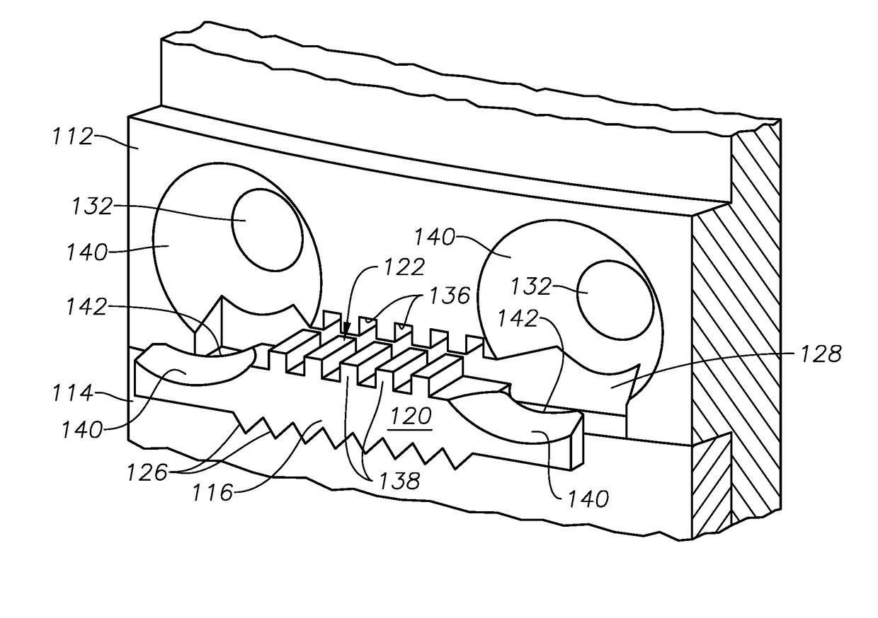
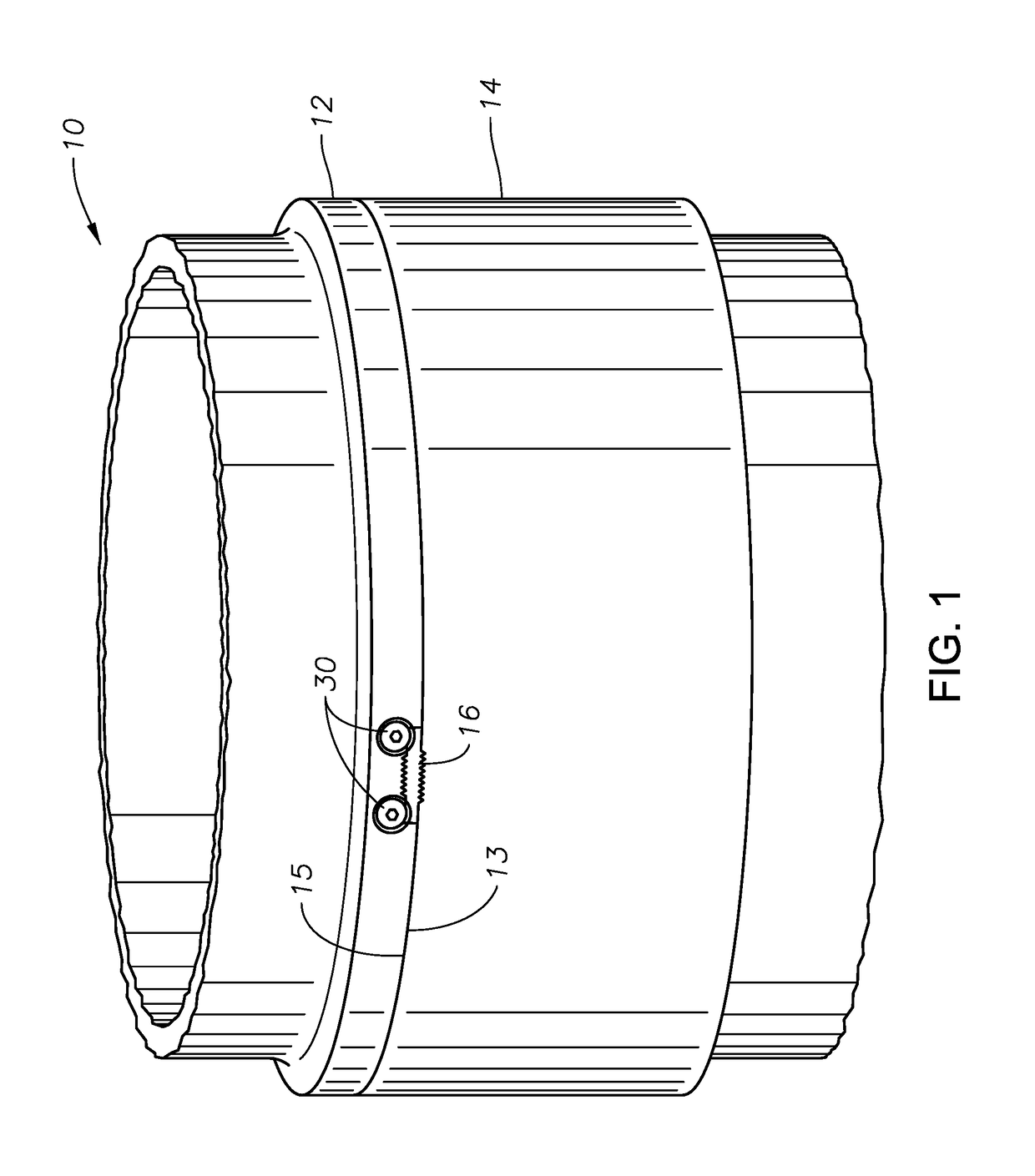
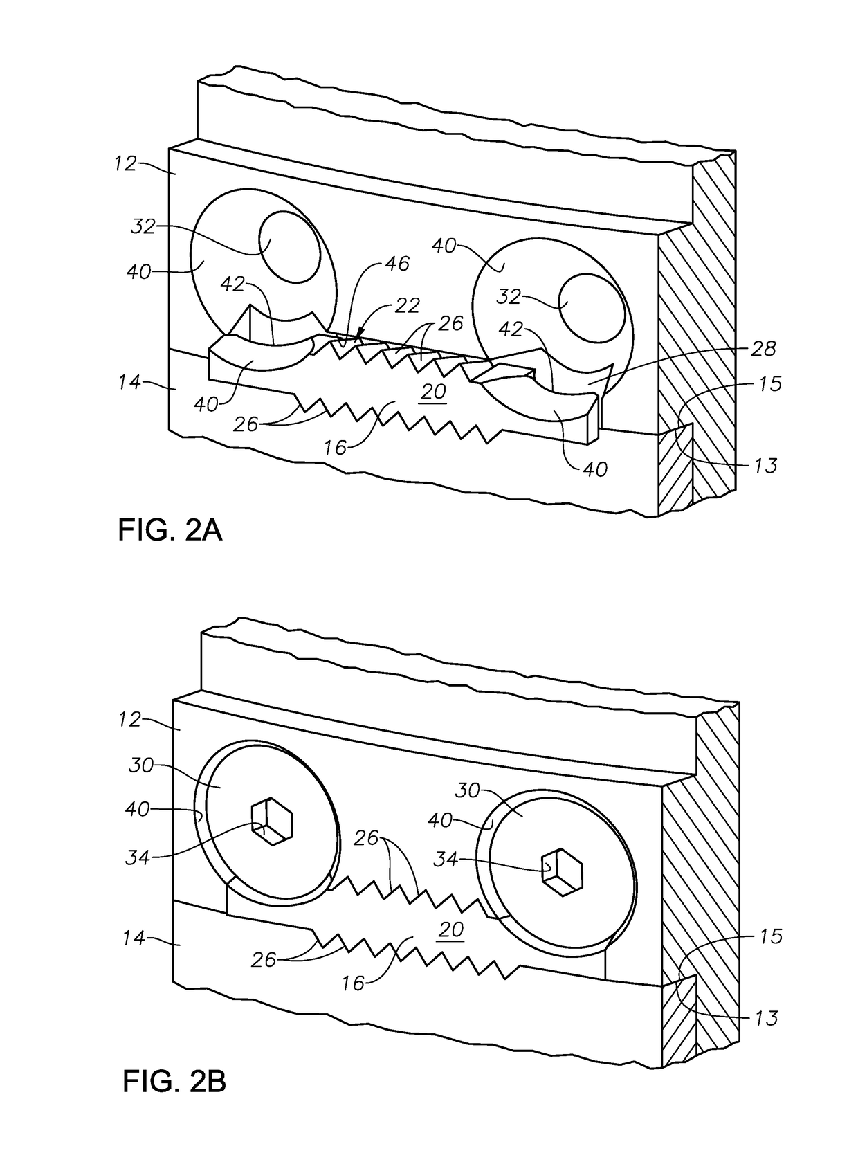
[0024]FIG. 1 is a perspective view of one example of a pipe connector locking system 10 according to the present technology, including a first pipe connector 12, a second pipe connector 14, and a key 16. The first and second pipe connectors 12, 14 are configured to engage one another and become attached. For example, the first pipe connector 12...


PUM


Abstract

A system for joining pipe segments, the system including a first pipe connector connected to a first pipe segment, and a second pipe connector threadingly connectable to the first pipe connector, and connected to a second pipe segment. The system further includes a recess in the outer surface of the first pipe connector, and an elongated key having first and second lengthwise surfaces. One of the lengthwise surfaces has protrusions that embed into a transverse surface of the second pipe connector when the key is mounted into the recess. The thickness of the key decreases with distance radially inward from the outer surface.

Description

BACKGROUND OF THE INVENTION[0001]1. Field of the Invention[0002]This technology relates to oil and gas wells, and in particular to pipe connectors within the wells.[0003]2. Brief Description of Related Art[0004]Typical oil and gas wells include strings of pipe that extend into the well in conjunction with drilling, casing, and production operations. These strings of pipe generally consist of discrete pipe segments that are joined together by pipe connectors as the pipe is run into the well. The pipe connectors may be threaded, with adjacent connectors having male and female threads configured to engage and join the pipe. Generally, the pipe end having the male thread is known as the pin, and the pipe end having the female thread is known as the box. When joining the pipe segments, it is desirable to limit circumferential movement between the connectors so that the connectors remain firmly attached. To limit such circumferential movement, a lock key may be employed.[0005]Some known l...

Claims


Application Information

Patent Timeline
Patent Type & Authority Patents(United States)
IPC IPC(8): F16L15/08E21B17/046E21B17/043
CPCF16L15/08E21B17/043E21B17/046E21B17/0465
Inventor O'DELL, KEVIN E.STEEN, THOMAS L.PALLINI, JOSEPH W.PETERS, STEPHEN D.PATTERSON, JR., WILLIAM R.
Owner VETCO GRAY
Learn More