Adaptable mounting system for phonograph records and/or various planar objects

a technology for adaptable mounting systems and phonograph records, which is applied in the direction of instruments, picture frames, show cards, etc., can solve the problems of failure of display and removal objectives of devices, high manufacturing costs, and inability to adap

a technology for adaptable mounting systems and phonograph records, which is applied in the direction of instruments, picture frames, show cards, etc., can solve the problems of failure of display and removal objectives of devices, high manufacturing costs, and inability to adap

US9717353B1Active Publication Date: 2017-08-01BORRA BRIAN

Image

  • Adaptable mounting system for phonograph records and/or various planar objects
  • Adaptable mounting system for phonograph records and/or various planar objects
  • Adaptable mounting system for phonograph records and/or various planar objects

Examples


first embodiment

Operation-First Embodiment

[0047]At present I believe that this embodiment operates most efficiently, but the other embodiments are also satisfactory.

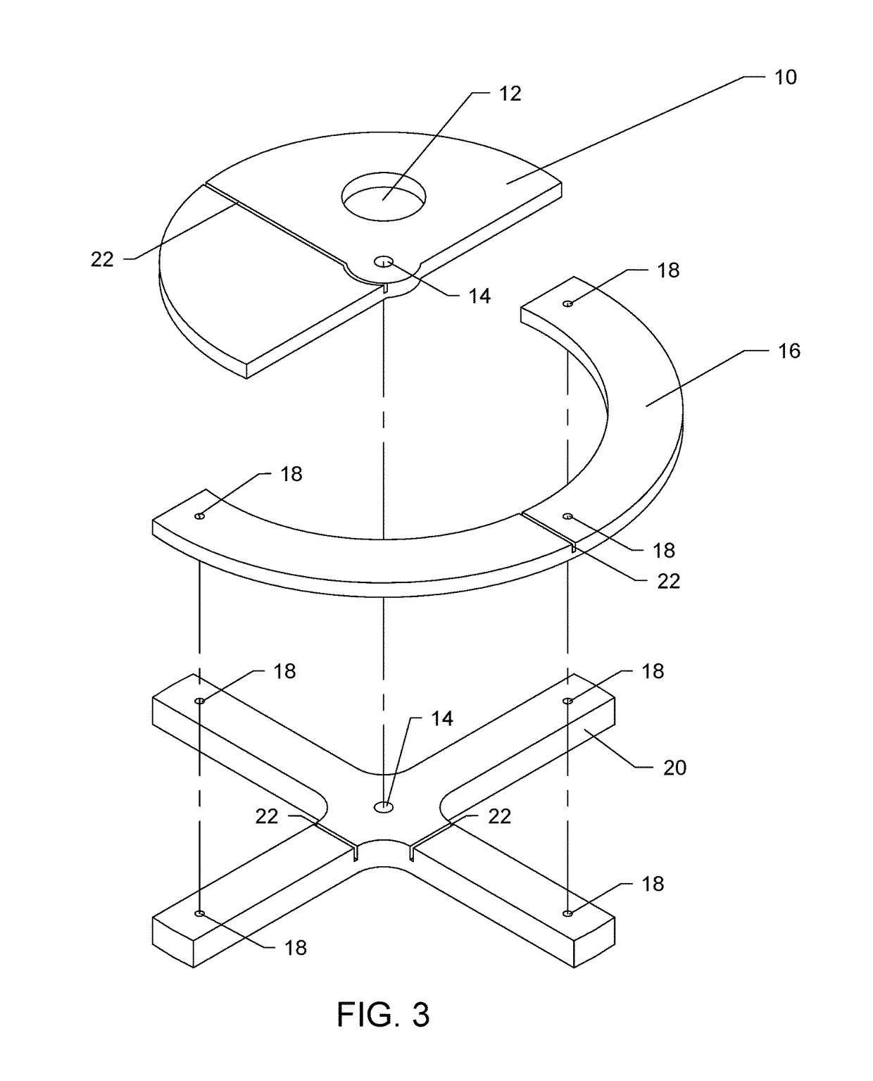
[0048]The inner retaining / semi-circular dial 10 is allowed to pivot about the center hole 14 allowing two modes of constraint—fixed or free. This action is initiated by the user, wherein one places their finger into gripping point 12 and rotates inner retaining dial 10 into either fixed or free position. In order for rotational operation to be achieved, the self-tapping screw through center hole 14 should be set to the correct torque, such that the inner retaining dial 10 is allowed to rotate about center hole 14. If the self-tapping screw is too tight, the inner retaining dial 10 won't be able to spin, if too loose, the dial won't stay at its last position or worse won't securely constrain a planar article.

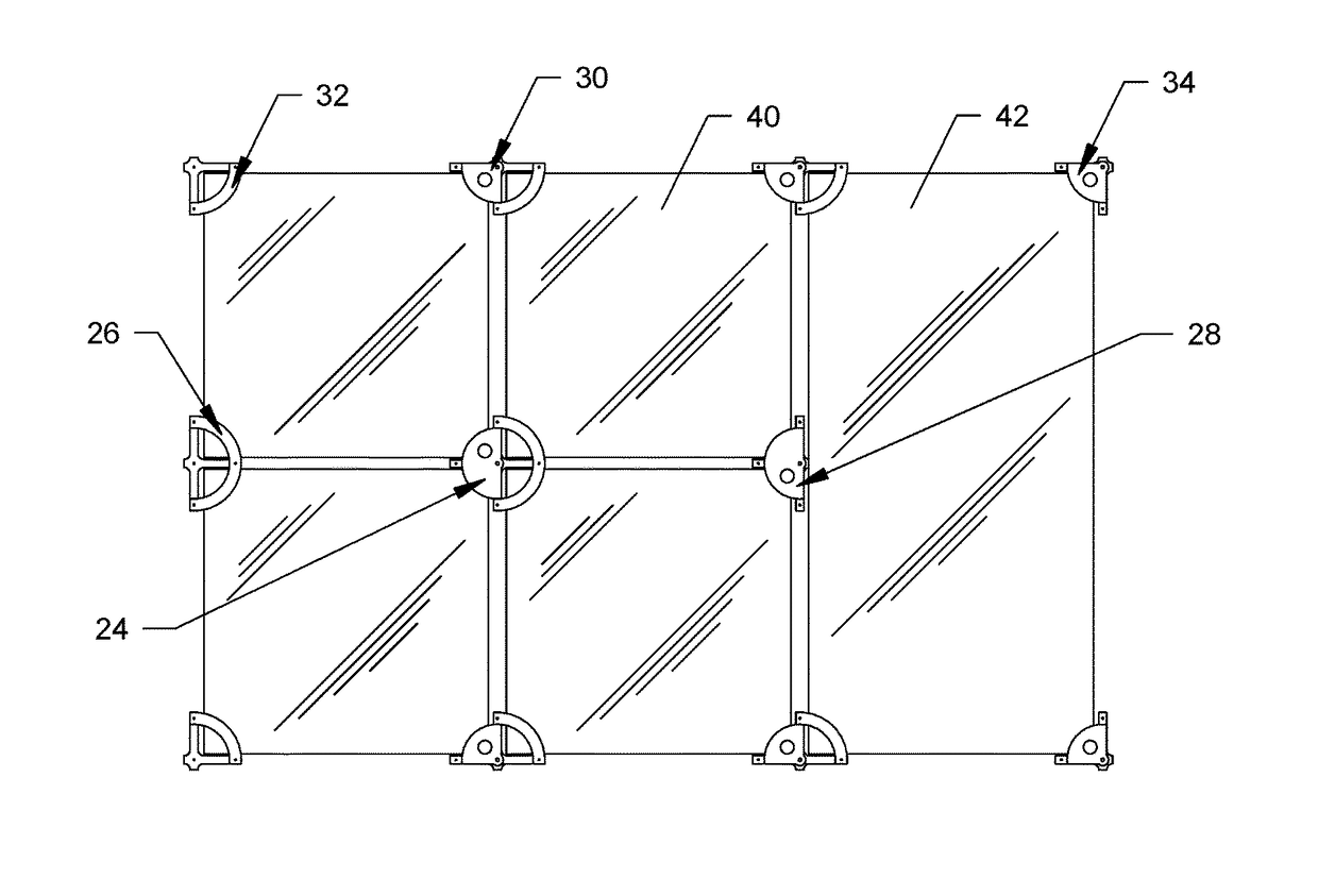
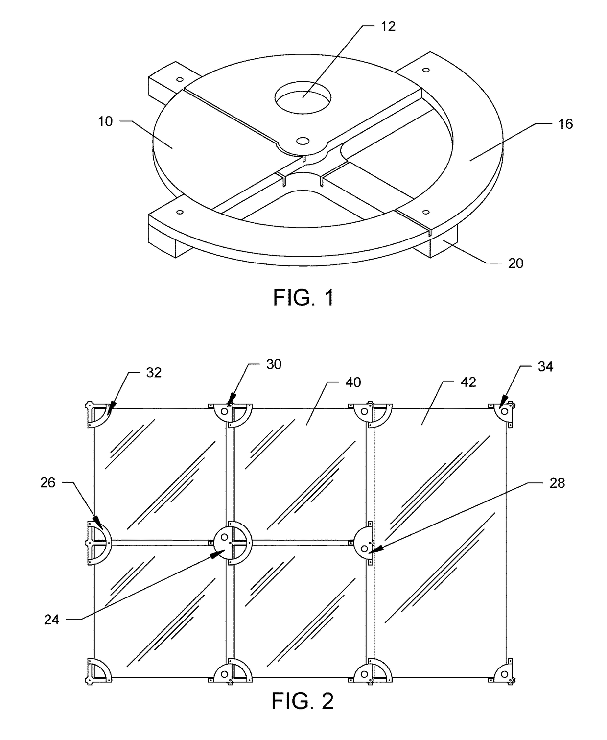
[0049]It takes four of the adapted assembled units, two of 32 and two of 34, to support all four corners of a single record / square ...


PUM


Abstract

In accordance with one embodiment, I presently contemplate a cruciform support base (20), semi-circular dial (10), and concentric semi-circular brace (16) that work together to support the corner of a record and / or planar article. The dial (10) and brace (16) are fastened to the support base (20) and machined in such a way that they form a simple, economical, and adaptable mechanical unit (24). Once paired with a minimum number of units, and mounted to a wall, they cooperate to display any number of records, planar articles, and / or combination thereof in an attractive, tight, grid-like configuration. Furthermore, the design of this system also allows for any one record and / or planar article to be easily retrieved or stored with the swipe of a finger.

Description

BACKGROUND—PRIOR ART[0001]Wall mounted frames provide a method for showcasing and storing planar articles. Specifically, these frames provide room decoration, openly displaying collections of a particular artist, genre, taste, or rarity and protection from damage or improper storing. Typically multiple articles are positioned in a grid-like fashion to achieve a collage effect.[0002]Previous display frames for phonograph records, or like planar articles, lack the ability to efficiently remove, insert, and display items one wishes to access; this embodiment permits all of these operations with a single, novel and adaptable mechanism. This was the motivation behind this invention; I couldn't find anything that suited these requirements.[0003]Many prior art patents exist, as the first phonographic record is over 100 years old (U.S. Pat. No. 564,586-1896), but such display frames do not provide a solution as adaptable, simple, and economical as the ensuing embodiment herein. Below is a t...

Claims


Application Information

Patent Timeline
01 Aug 2017
Publication
US9717353B1
IPC
A47G29/02; A47G1/06; F16M13/02; A47G1/17; A47G1/16
CPC
A47G1/17; A47G1/06; A47G1/164; F16M13/02; A47G2001/0672; A47G1/215; G09F1/00
Inventors
BORRA, BRIAN MARTIN