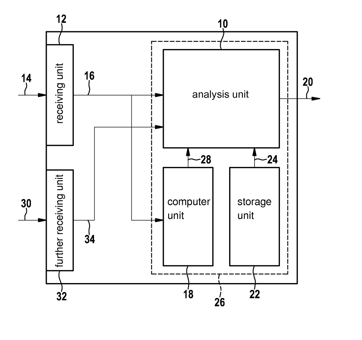

Monitoring device for at least one subunit of a hydraulic braking system and method for examining a functional capability of at least one subunit of a hydraulic braking system

a technology of hydraulic braking system and monitoring device, which is applied in the direction of braking system, braking components, instruments, etc., can solve problems such as inconvenient analysis, and achieve the effect of minimizing the risk, maximizing the robustness of monitoring, and minimizing the risk of incorrect monitoring respons

Active Publication Date: 2017-08-01
ROBERT BOSCH GMBH
View PDF43 Cites 1 Cited by
  • Summary
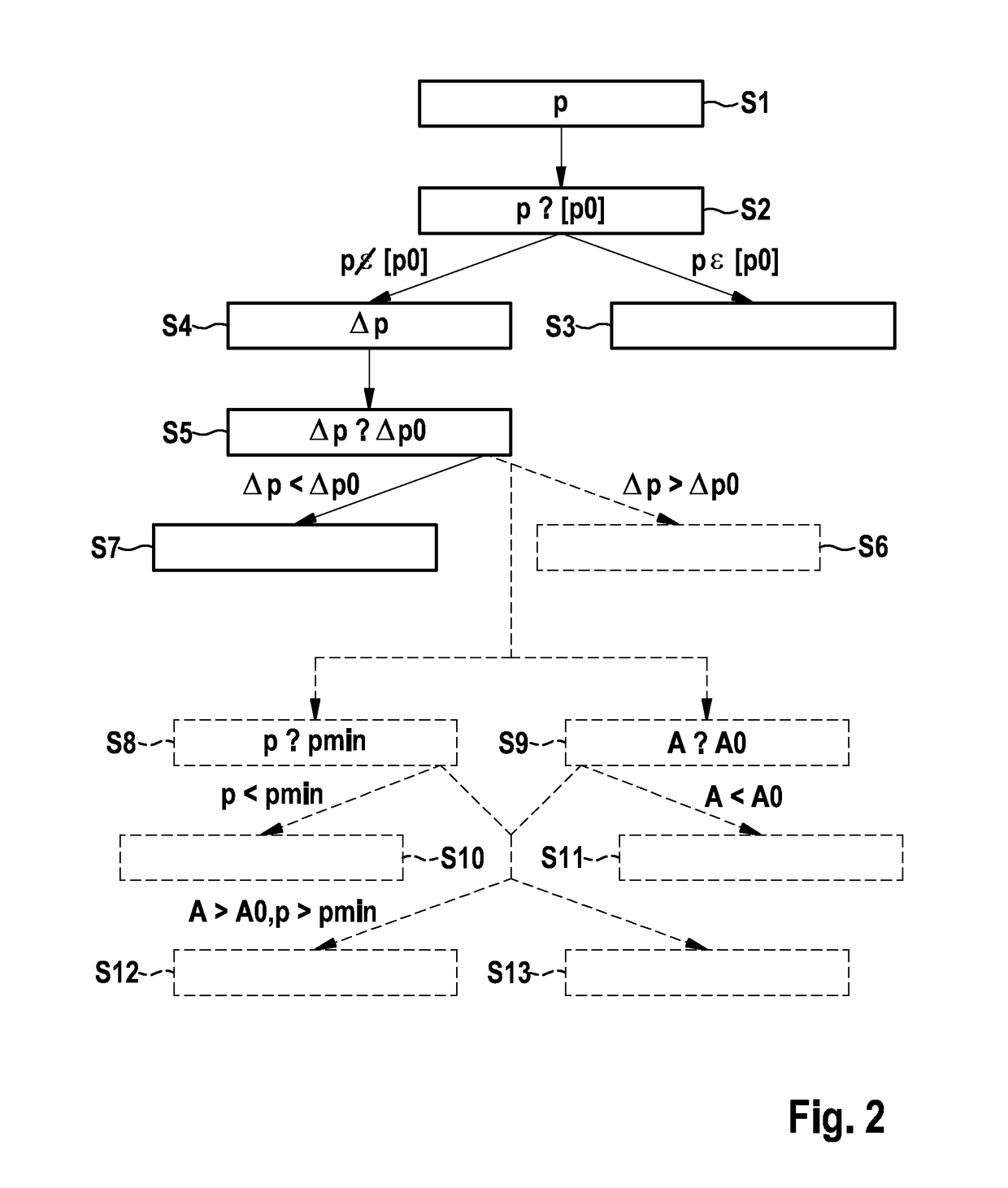
  • Abstract
  • Description
  • Claims
  • Application Information

AI Technical Summary

Benefits of technology

[0006]The present invention implements a maximum recognition quality in the monitoring / examining of at least one subunit of a hydraulic braking system. It may be ensured by this maximum recognition quality that a fault present in at least the subunit and / or a functional impairment of at least the subunit is recognizable rapidly. At the same time, the present invention ensures maximum robustness of the monitoring. In particular, the risk of incorrect response from the monitoring may be minimized with the aid of the monitoring device according to the present invention and the corresponding method for examining at least one subunit of a hydraulic braking system. This minimization of the risk is also ensured in the event of unfavorable hardware tolerances and disadvantageous operating states.
[0007]With the aid of the present invention, a monitoring function or an examining function may be designed more robustly, in that not only an absolute deviation of the pressure variable (actual pressure variable) from the comparative value range (the at least one setpoint pressure variable) is considered, but rather, at least in the case of a deviation beyond a deviation limit, a behavior of at least the subunit of the hydraulic braking system is also used for the evaluation. In particular, with the aid of the present invention, the pressure adaptation behavior of at least the subunit of the hydraulic braking system may be used, with the aid of which the presence of a fault / a functional impairment of at least the subunit of the hydraulic braking system is recognizable in a simple way.
[0008]It is to be noted that the implementability of the present invention only requires the sensor for providing the pressure variable as a sensor unit. Therefore, the necessity is dispensed with of additionally situating still a further sensor, for example, for measuring a temperature, on the braking system in addition to the at least one sensor for providing the pressure variable. In relation to conventional monitoring of a braking system on the basis of items of sensor information and / or models which are calculated / analyzed in a control unit, the present invention therefore offers the advantage that both the items of sensor information and the items of model information may be omitted. In this way, a substantial savings is ensured in hardware and development costs on the monitored / examined braking system, or on the at least one subunit of the braking system. In particular, the present invention, as explained in greater detail hereafter, may also differentiate a temperature-related pressure deviation from a non-temperature-related pressure deviation without direct consideration of the temperature prevailing in the hydraulic braking system. Therefore, if the present invention is used, the requirement of using conventional expensive hardware for recognizing temperature-dependent effects in a conventional braking system is also omitted in particular. Since the simulation of temperature-dependent effects in a hydraulic braking system is only implementable in sufficient quality with a comparatively high expenditure, the complex electronics for the conventional recognition of temperature-dependent effects may therefore be saved with the aid of the present invention. In addition, the present invention reduces the complexity of the monitoring or examining steps which are conventionally to be executed to monitor / examine a braking system, which is frequently linked to a positive influence on the product quality.

Problems solved by technology

As explained in greater detail hereafter, in particular disregarding the measuring time of a compared pressure variable may conventionally result in an incorrect analysis result.

Method used


Image

  • Monitoring device for at least one subunit of a hydraulic braking system and method for examining a functional capability of at least one subunit of a hydraulic braking system
  • Monitoring device for at least one subunit of a hydraulic braking system and method for examining a functional capability of at least one subunit of a hydraulic braking system
  • Monitoring device for at least one subunit of a hydraulic braking system and method for examining a functional capability of at least one subunit of a hydraulic braking system

Examples


Embodiment Construction

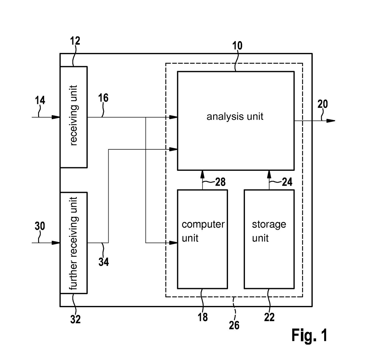
[0013]FIG. 1 shows a schematic view of one exemplary embodiment of the monitoring device according to the present invention.

[0014]At least one subunit of a hydraulic braking system may be monitored with the aid of the monitoring device which is schematically shown in FIG. 1. Monitoring the at least one subunit may be understood, for example, as examining or checking the at least one subunit. The at least one subunit, which may be monitored, of the hydraulic braking system may therefore be, for example, an actuator / a final controlling device, for example, a pump, a plunger, a continuously adjustable / variable / controllable valve, and / or a storage chamber, in particular a high-pressure accumulator having a valve. With the aid of the monitoring device, it may be ascertained in particular whether the actuator or the final controlling device provides at least a minimum performance of a setpoint performance predefined by a controller. The usability of the monitoring device is not restricted...


PUM


Abstract

A monitoring device for, and a method for examining a functional capability of, at least one subunit of a hydraulic braking system includes: ascertaining at least one pressure variable of a pressure prevailing in the hydraulic braking system, and comparing the ascertained pressure variable to a predefined comparative value range, at least if the ascertained pressure variable deviates from the predefined comparative value range, a pressure change variable with respect to a time change of the pressure variable being ascertained and the ascertained pressure change variable being compared to a predefined minimum change variable, and the functional capability being established in consideration of the comparison of the pressure variable to the predefined comparative value range, and, at least if the ascertained pressure variable deviates from the predefined comparative value range, in consideration of the comparison of the pressure change variable to the predefined minimum change variable.

Description

CROSS REFERENCE TO RELATED APPLICATION[0001]The present application is the national stage entry of International Patent Application No. PCT / EP2012 / 058601, filed on May 10, 2012, which claims priority to Application No. DE 10 2011 078 890.5, filed in the Federal Republic of Germany on Jul. 8, 2011.FIELD OF INVENTION[0002]The present invention relates to a monitoring system for at least one subunit of a hydraulic braking system. Furthermore, the present invention relates to a method for examining a functional capability of at least one subunit of a hydraulic braking system.BACKGROUND INFORMATION[0003]A braking system and a method for operating a braking system are described in German Application No. DE 10 2008 003 664. The affected braking system may have at least one pressure sensor, which is connected to a subunit of the braking system. With the aid of the pressure sensor, a pressure in the affected section of the braking system may be measured. In particular, the measured pressure ...

Claims


Application Information

Patent Timeline
Patent Type & Authority Patents(United States)
IPC IPC(8): G06F7/00B60T8/88B60T17/22
CPCB60T17/221B60T8/885B60T17/22B60T2270/403B60T2270/404B60T2270/413
Inventor KUNZ, MICHAELKINDER, RALFSPOERI, TOBIAS
Owner ROBERT BOSCH GMBH
Learn More