Method for decoding an RF signal bearing a sequence of symbols modulated by CPM and associated decoder

Active Publication Date: 2022-11-08
RIVIERAWAVES
View PDF11 Cites 0 Cited by
  • Summary
  • Abstract
  • Description
  • Claims
  • Application Information

AI Technical Summary

Benefits of technology

[0042]As shown by the simulation results discussed below with reference to FIGS. 2 and 3, the method as introduced above allows a performance gain compared to the LDI demodulator, while restricting complexity on a linear scale per received symbol. It allows estimating the set of variables and parameters {a1, . . . , an, h, ω, Φ0} with minimum latency, minimum Mean Squared Error (MSE) and maximum robustness against interferences.

Problems solved by technology

It shows a very low complexity, but suffers from a considerable loss (>6 dB) over the optimal receiver.
On the contrary, the optimal receiver has an extremely high complexity in particular when some impairments / mismatches, such as frequency offset, have to be estimated jointly along with the demodulation.

Method used


Image

  • Method for decoding an RF signal bearing a sequence of symbols modulated by CPM and associated decoder
  • Method for decoding an RF signal bearing a sequence of symbols modulated by CPM and associated decoder

Examples


Embodiment Construction

[0071]The following detailed description of the invention refers to the accompanying drawings. While the description includes exemplary embodiments, other embodiments are possible, and changes may be made to the embodiments described without departing from the spirit and scope of the invention.

[0072]Herein a system of equations may be defined as a finite set of equations for which common solutions exist.

[0073]The term “training symbol” denotes a symbol making part of the sequence of symbols to be retrieved at the level of the receiver and already known by the receiver.

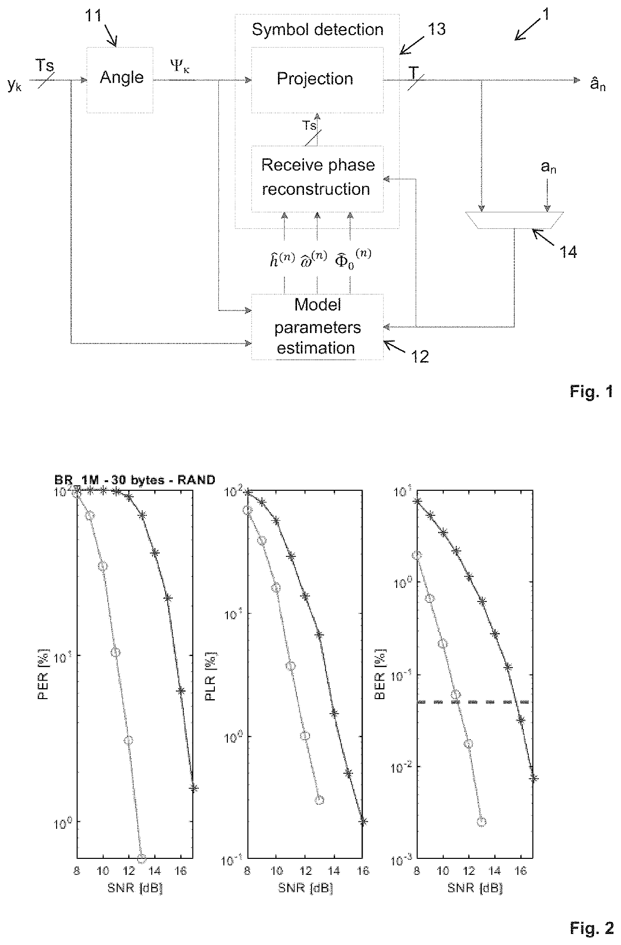
[0074]FIG. 1 shows an example architecture of a receiver 1 designed for implementing the decoding method according to the first aspect of the invention.

[0075]As shown in FIG. 1, such architecture may comprise at least:[0076]A phase extractor 11 depicted by the “angle” block,[0077]An estimator 12 of the model parameters {h, ω, Φ0} depicted by the “Model parameters estimation” block,[0078]A symbol detector 13 depicted by...


PUM


Abstract

A method for decoding an RF signal bearing a sequence of transmitted symbols modulated by CPM. The method includes, at the receiver: estimating model parameters {h, ω, Φ0} among which h characterizes a modulation index, ω characterizes a carrier frequency offset and Φ0 characterizes an initial phase offset, and detecting received symbols corresponding to said transmitted symbols of the sequence, wherein, at time nT where T is a symbol duration, the parameters {h, ω, Φ0} are estimated by solving a system of three linear equations whose: three unknowns {ĥ(n), {circumflex over (ω)}(n), {circumflex over (Φ)}0(n)} are respectively function of said model parameters {h, ω, Φ0}, and coefficients {B(n), C(n), D(n), F(n), G(n), H(n), v1(n), v2(n), v3(n)} are computed in a recursive way in function of: a sequence of symbols {ân} corresponding to the sequence of transmitted symbols up to time nT, and measured phases {Ψk} of samples {yk} of the RF signal received from time (n−1)T to time nT.

Description

FIELD[0001]One or more embodiments of the present invention generally relate to a method for decoding symbols coded by using the so-called CPM (Continuous Phase Modulation) scheme. More specifically one or more embodiments relate to such a method developed for some Bluetooth® standards, and for Bluetooth BR (Basic Rate) and BLE (Bluetooth Low Energy).BACKGROUND[0002]CPM is widely used in communications for their power and spectral efficiency.[0003]Advantageously, those communications can be easily demodulated using a simple discriminator receiver. This demodulator usually referred to as LDI, is based on a Limiter-Discriminator Integrator. It shows a very low complexity, but suffers from a considerable loss (>6 dB) over the optimal receiver.[0004]On the contrary, the optimal receiver has an extremely high complexity in particular when some impairments / mismatches, such as frequency offset, have to be estimated jointly along with the demodulation.[0005]Bluetooth BR and BLE modulatio...

Claims


Application Information

Patent Timeline
Patent Type & Authority Patents(United States)
IPC IPC(8): H04L27/20H04B7/06
CPCH04L27/2014H04B7/0639H04B7/0663H04L27/22H04L27/14H04L27/2017
Inventor BAZZI, AHMADMEILHAC, LISA
Owner RIVIERAWAVES
Why Eureka
Try Eureka