Earth working machine having a filtered dust extraction system with an elastically deformable filter housing

a technology of filter housing and earthwork machine, which is applied in the direction of filtration separation, separation process, and way, etc., can solve the problems of dust contaminating the air, high moisture content of extracted dust-laden air, and damp dust itself, etc., and achieves the effect of easy and reliable removal

Active Publication Date: 2021-12-21
WIRTGEN GMBH
View PDF12 Cites 0 Cited by
  • Summary
  • Abstract
  • Description
  • Claims
  • Application Information

AI Technical Summary

Benefits of technology

[0015]The object of the present invention is therefore to refine the aforementioned mobile earth working machine in such a way that even consolidated, hardened particle material can be easily and reliably removed from its filter apparatus.
[0017]For easier deformability of the at least one wall of the filter housing, that wall can be constituted from a material having a lower modulus of elasticity than other walls, wall portions, or housing portions of the filter housing. In the interest of maximum robustness of the filter housing, the latter is constituted to the greatest possible extent from metal, in particular sheet metal. The at least one deformable wall of the filter housing can be constituted from a plastic, in particular an elastomer, for instance vulcanized rubber or silicone rubber, or can encompass such a material at least in portions.
[0019]In an advantageous refinement of the invention, the earth working machine can comprise a conveying fan for conveying the dust-laden air, the filter apparatus, in particular the filter element, preferably being located on the intake side of the conveying fan so that the air conveyed by the conveying fan reaches the conveying fan in a cleaned state. The fewer dust particles contained in the conveyed air, the less the abrasive effect of the conveyed air on the conveying fan. The conveying fan can encompass an axial fan that is robust with respect to dust-laden air. Alternatively, the conveying fan can encompass a radial fan that occupies less installation space than an axial fan having the same conveying performance.
[0026]In order to remove dedusted dust particle material from the filter housing, whether dust particle material from the filter element or material from a wall of the filter housing, the filter housing can comprise an outlet configuration displaceable between an open position and a closed position, for example a movable and / or deformable portion of a filter housing floor which, in its open position, opens an outlet opening in the filter housing. Dust particle material that has collected in the filter housing can be removed from the filter housing through the outlet opening. At least the floor of the filter housing is preferably embodied as the above-described deformable wall, so as thereby to allow the outlet opening also to be embodied without an excessive increase in the number of components required.
[0027]As has already been mentioned above, the earth working machine preferably comprises a transport apparatus with which substrate material removed by the working apparatus is conveyable away from the working apparatus to a delivery location. In order for the quantities of removed substrate material which occur per unit time to be reliably transported away, the transport apparatus preferably encompasses as a transport means at least one conveyor belt, preferably at least two conveyor belts that follow one in a conveying direction, which, in order to reduce dust contamination of the surroundings of the earth working machine, is / are enclosed over at least 90% of its / their conveying length. Other transport apparatuses, however, for example screw conveyors and the like, are nevertheless also not excluded.
[0035]In order to reduce stress on the filter element of the filter apparatus during filtering operation, the filter apparatus can comprise a prefilter that is different from the filter element and is arranged preferably outside the filter housing, so that only pre-cleaned dust-laden air is directed to the filter element. So-called “cyclone” filters, which remove dust particles above a specific particle size from the dust-laden air, have proven successful as such prefilters. The result is that, preferably, only dust particles below a specific particle size, or a specific particle size range, reach the at least one filter element in the filter housing. The filter material of the filter element can be particularly well matched, in terms of its porosity and its permeability, to the particle size range of the dust particles in the pre-cleaned air, so that the cleaning effect of the filter element can be further enhanced.

Problems solved by technology

This dust contaminates the air extracted by the extraction device.
A further problem with the filter apparatus can be that the extracted dust-laden air can have a high moisture content and / or that the dust itself is damp.
This moisture in the dust-laden air can cause dust and filter cake to become consolidated in the filter housing.
Because the dust and the filter cake forming therefrom are predominantly mineral in nature, additional moisture often causes the moist filter cake to harden in mortar-like fashion.

Method used


Image

  • Earth working machine having a filtered dust extraction system with an elastically deformable filter housing
  • Earth working machine having a filtered dust extraction system with an elastically deformable filter housing
  • Earth working machine having a filtered dust extraction system with an elastically deformable filter housing

Examples


Embodiment Construction

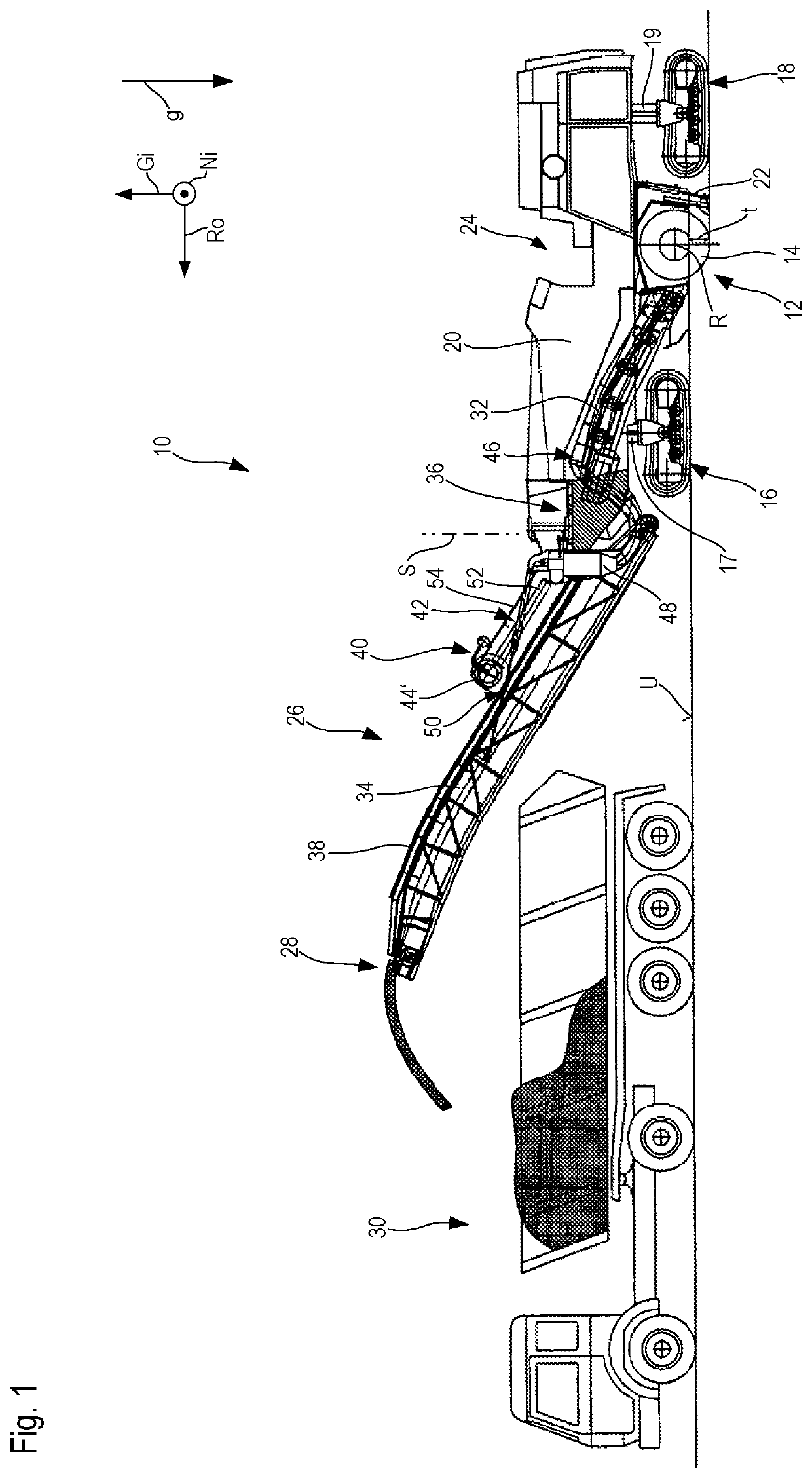
[0044]In FIG. 1, an earth working machine (hereinafter referred to simply as a “machine”) according to the present invention is labeled in general with the number 10. What is depicted by way of example as machine 10 according to the present invention is a large road milling machine, working apparatus 12 of which, having a milling drum 14 known per se as is typical for large road milling machines, is arranged between front drive units 16 and rear drive units 18. Drive units 16 and 18, each drivable for propelled motion preferably by a hydraulic motor (not depicted), are steerable, and carry a machine frame 20 that in turn carries working apparatus 12. Machine 10 is thus a self-propelled vehicle.

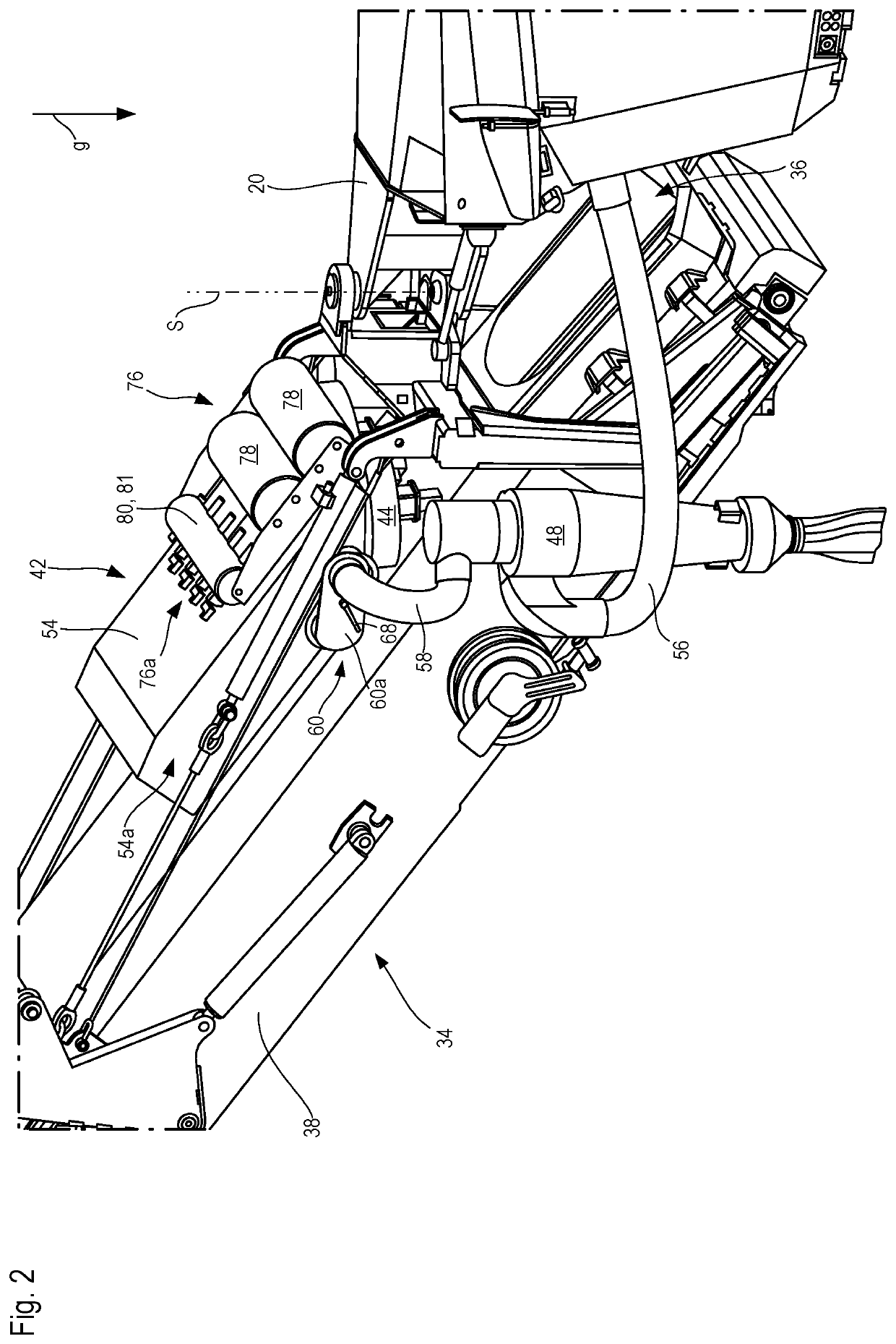
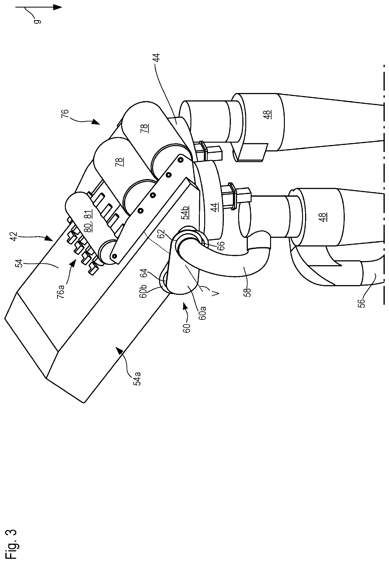
[0045]The direction of gravity is labeled with an arrow g in FIGS. 1 to 3.

[0046]Milling drum 14, rotatable around a rotation axis R that is orthogonal to the drawing plane of FIG. 1 and proceeds parallel to pitch axis Ni of machine 10, is shielded with respect to the external surroundings of m...


PUM

PropertyMeasurementUnit
transfer forceaaaaaaaaaa
modulus of elasticityaaaaaaaaaa
air pressureaaaaaaaaaa

Abstract

A mobile earth working machine (10), for example a road milling machine, recycler, or surface miner, includes:a working apparatus (12) for material-removing working of a region of a substrate (U); andan extraction device (40) that is embodied to extract dust-laden air from at least one machine region at at least one extraction location (46), and to exhaust extracted air at a discharge location (50) different from the extraction location (46),the extraction device (40) comprising a filter apparatus (42) arranged along an operational flow path from the at least one extraction location (46) to the discharge location (50), the filter apparatus (42) encompassing:a filter housing (54);a filter element (52) received in the filter housing (54), the filter element (52) being embodied to remove dust particles from the air flowing through the filter apparatus (42). The filter apparatus (42) comprises a deformation actuator arrangement (44, 76a) that interacts force-transferringly with at least one wall (86) of the filter housing (54) in such a way that by actuation of the deformation actuator arrangement (44, 76a), the at least one wall (86) of the filter housing (54) is deformable orthogonally to its wall surface.

Description

CROSS-REFERENCES TO RELATED APPLICATIONS[0001]This application claims benefit of German Patent Application No. DE 10 2019 132 892.6, filed on Dec. 3, 2019, and which is hereby incorporated by reference in its entirety.BACKGROUND OF THE INVENTIONField of the Invention[0002]The present invention relates to a mobile earth working machine, for example a road milling machine, a recycler, or a surface miner, the earth working machine encompassing:[0003]a working apparatus for material-removing working of a region of a substrate; and[0004]an extraction device that is embodied to extract dust-laden air from at least one machine region at at least one extraction location, and to exhaust extracted air at a discharge location different from the extraction location,[0005]the extraction device comprising a filter apparatus arranged along an operational flow path from the at least one extraction location to the discharge location, the filter apparatus encompassing:[0006]a filter housing; and[0007...

Claims


Application Information

Patent Timeline
Patent Type & Authority Patents(United States)
IPC IPC(8): E01C23/088B01D46/08E01C23/12B01D46/04E21C35/22B01D46/10E01C23/09
CPCE01C23/088B01D46/04B01D46/08E01C23/127E21C35/223B01D46/103E01C23/0933E01C2301/50B01D46/4227B01D46/0046B01D29/70B01D29/66E01C21/00E21C47/00B28D7/02B65G69/18
Inventor DRUMM, STEPHAN
Owner WIRTGEN GMBH
Why Eureka
Try Eureka