Component measuring device

a technology of component measuring and measuring device, which is applied in the direction of optical radiation measurement, instruments, spectrometry/spectrophotometry/monochromator, etc., can solve the problems of blood applied to the test strip, dust or foreign matter tends to be trapped in the photometric unit, and achieves high measurement accuracy

Active Publication Date: 2009-09-08
TERUMO KK
View PDF39 Cites 6 Cited by
  • Summary
  • Abstract
  • Description
  • Claims
  • Application Information

AI Technical Summary

Benefits of technology

[0015]It is an object of the present invention to provide a component measuring device having high measurement accuracy.
[0016]Another object of the present invention is to provide a component measuring device having high measurement accuracy, which is capable of accurately detecting a stain on a light-transmissive member.
[0018]With this arrangement, dust, blood (specimen), or the like is reliably prevented from entering into the passage in the photometric unit (into the photometric unit). Even if dust, the specimen, or the like is applied to an end of the photometric unit or the like, it can easily and reliably be removed. Therefore, the amount of a blood component in question can be measured with high measurement accuracy.
[0020]With this arrangement, dust, blood (specimen), or the like is reliably prevented from entering into the passage in the photometric unit (into the photometric unit). Even if dust, the specimen, or the like is applied to an end of the photometric unit or the like, it can easily and reliably be removed. Therefore, the amount of a blood component in question can be measured with high measurement accuracy.
[0034]With this arrangement, a stain on the light-transmissive member can be detected with high accuracy. Since an amount of a blood component in question is prevented from being measured while the light-transmissive member is being stained, the measurement accuracy is increased. Since the component measuring device has the light-transmissive member, dust, the specimen, or the like is reliably prevented from entering into the passage in the photometric unit (into the photometric unit), so that an amount of a blood component in question can be measured with high measurement accuracy.
[0039]With this arrangement, a stain on the light-transmissive member can be detected with high accuracy. Since an amount of a blood component in question is prevented from being measured while the light-transmissive member is being stained, the measurement accuracy is increased. Since the component measuring device has the light-transmissive member, dust, the specimen, or the like is reliably prevented from entering into the passage in the photometric unit (into the photometric unit), so that an amount of a blood component in question can be measured with high measurement accuracy.

Problems solved by technology

The photometric unit of the above component measuring device suffers a problem in that dust or foreign matter tends to be trapped in the photometric unit.
With the conventional blood glucose level measuring device, however, since the opening is not sealed in a liquid-tight manner, blood applied to the test strip may be trapped into the passage in the photometric unit, and it is difficult to remove the trapped blood from the test strip.
Furthermore, if a liquid such as water and an aqueous solution of ethanol is used to wash away a stain such as dust, blood, urine, and fingerprint, then the liquid may possibly enter the blood glucose level measuring device.
If foreign matter such as water and blood is introduced into the passage in the photometric unit, then the measured value of the blood glucose level varies, resulting in a reduction in the measurement accuracy.
The applied stains are liable to cause the measured value of the blood glucose level to vary, resulting in a reduction in the measurement accuracy.
According to the white level checking process for detecting a stain, however, the strong reflected light from the test strip and the weak reflected light from the stain on the transparent plate are mixed with each other, tending to fail to detect a stain on the transparent plate highly accurately.

Method used


Image

  • Component measuring device
  • Component measuring device
  • Component measuring device

Examples


first embodiment

[0109]A first embodiment of a component measuring device according to the present invention will be described below.

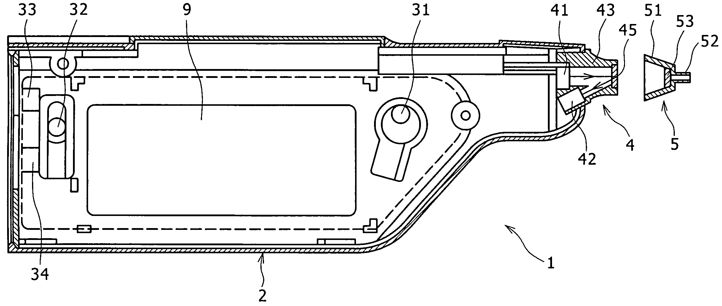
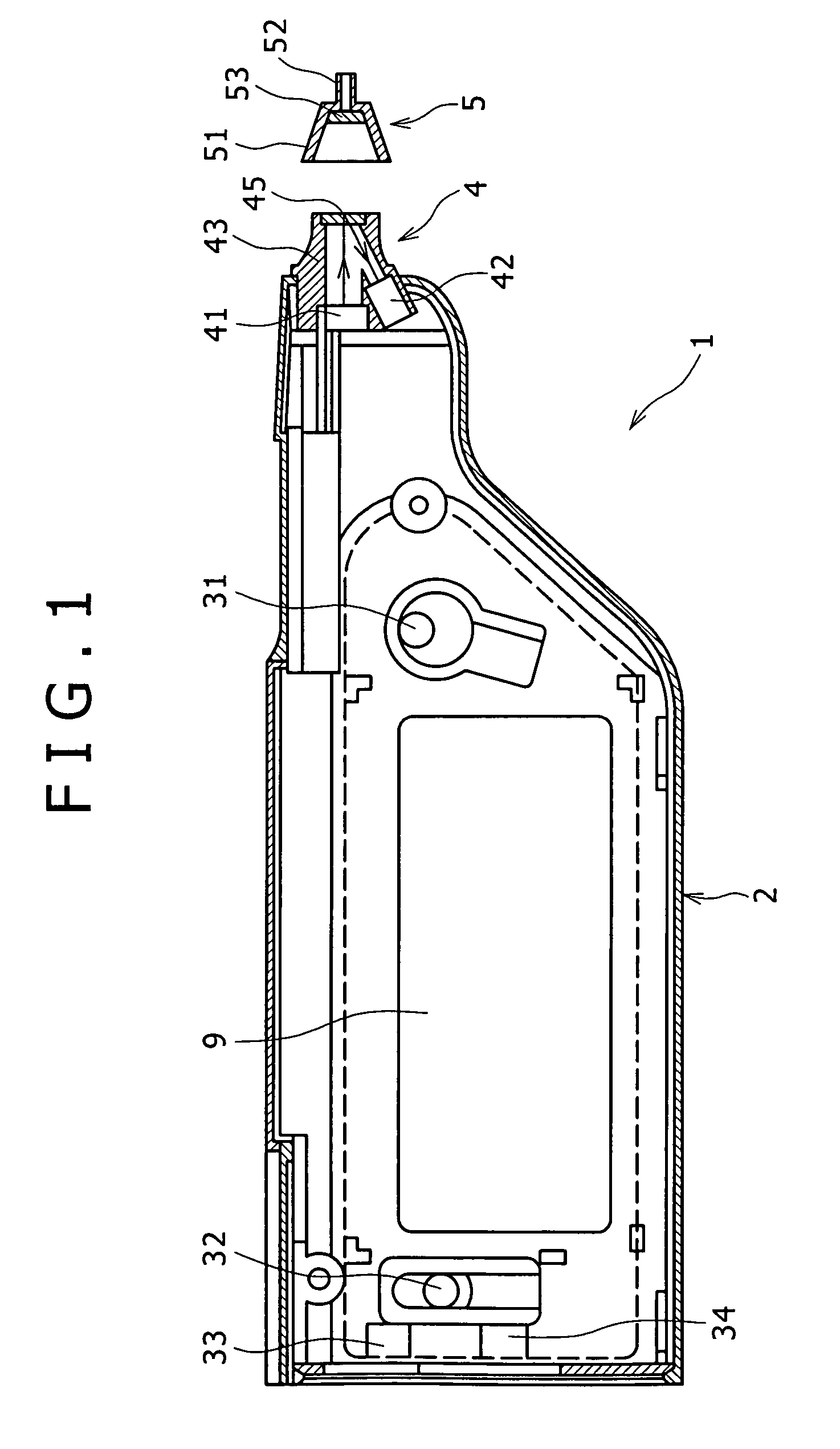
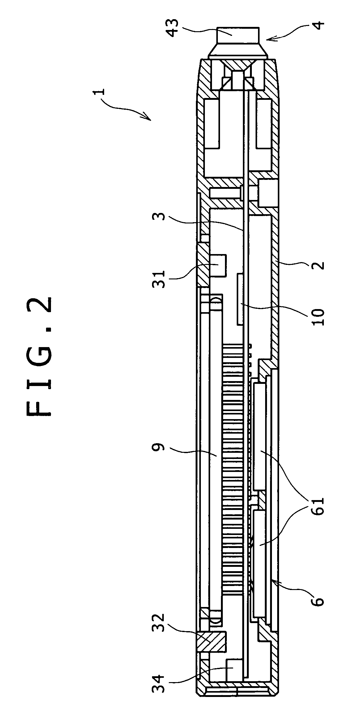
[0110]FIG. 1 is a plan view showing an internal structure of the first embodiment of the component measuring device according to the present invention, FIG. 2 is a sectional side elevational view of the component measuring device shown in FIG. 1, FIG. 3 is a block diagram of the component measuring device shown in FIG. 1, and FIG. 4 is a vertical cross-sectional view of a photometric unit of the component measuring device shown in FIG. 1. The left side in FIGS. 1, 2, and 4 will be referred to as “proximal end” and the right side as “distal end”.

[0111]The component measuring device (blood component measuring device) 1 shown in these figures has a casing 2 in which a printed-circuit board 3 is disposed. A photometric unit 4 is disposed in the distal end of the casing 2. A liquid crystal display (LCD) unit 9 is installed in a window of the casing 2.

[0112]Control means 10 ...

second embodiment

[0156]A second embodiment of a component measuring device according to the present invention will be described below.

[0157]FIG. 5 is a cross-sectional view showing the structure of the photometric unit of the second embodiment of the component measuring device according to the present invention.

[0158]The component measuring device according to the second embodiment will be described below basically with respect to differences thereof from the component measuring device according to the first embodiment, and identical parts will not be described below.

[0159]According to the second embodiment, the photometric unit 4 differs in structure. Other details of the second embodiment are identical to those of the first embodiment. Specifically, the photometric unit 4 shown in FIG. 5 differs from the photometric unit 4 according to the first embodiment in that a holder member 47 is added.

[0160]The holder member 47 serves to fix the light-transmissive member 45 to the holder 43. The holder memb...

third embodiment

[0174]A third embodiment of a component measuring device according to the present invention will be described below.

[0175]FIG. 6 is a cross-sectional view showing the structure of the photometric unit of the third embodiment of the component measuring device according to the present invention.

[0176]The component measuring device according to the third embodiment will be described below basically with respect to differences thereof from the component measuring devices according to the first and second embodiments, and identical parts will not be described below.

[0177]According to the third embodiment, the holder member 47 differs in structure. Other details of the third embodiment are identical to those of the second embodiment. Specifically, the photometric unit 4 shown in FIG. 6 differs from the photometric unit 4 according to the second embodiment in that the opening 472 defined in the holder member 47 has a different shape.

[0178]The opening 472 according to the present embodiment...


PUM

PropertyMeasurementUnit
distanceaaaaaaaaaa
cross-sectional areaaaaaaaaaaa
thicknessaaaaaaaaaa

Abstract

A component measuring device for measuring the quantity and / or the property of a given component in a specimen by calorimetrically measuring a test strip includes a tip mount on which is to be mounted a tip having the test strip, and a photometric unit. The photometric unit comprises a light-emitting element that applies light to the test strip while the tip is mounted on the tip mount, a light-detecting element that detects light reflected from the test strip, and a holder in which is held the light-emitting element and the light-detecting element. The holder possesses a passage through which passes the light and the reflected light. A light-transmissive member closes the passage with a sealing member interposed therebetween in a portion of the holder which faces the test strip. The component measuring device can also be provided with a stain detecting device which is adapted to detect a stain on the light-transmissive member.

Description

[0001]This application is the U.S. national stage application of International Application No. PCT / JP2004 / 007305 filed on May 21, 2004 designating the United States, the entire content of which is incorporated herein by reference. This application is also based on and claims priority under 35 U.S.C. § 119(a) to Japanese Application No. 2003-144131 filed on May 21, 2003, Japanese Application No. 2003-201933 filed on Jul. 25, 2003 and Japanese Application No. 2003-328879 filed on Sep. 19, 2003, the entire content of each of which is incorporated herein by reference.TECHNICAL FIELD[0002]The present invention relates to a component measuring device for measuring the quantity and / or the property of a component in question, such as for measuring a blood glucose level.BACKGROUND ART[0003]There is known a blood glucose level measuring device (blood component measuring device) for measuring a blood glucose level. The blood glucose level measuring device quantifies a blood glucose level by op...

Claims


Application Information

Patent Timeline
Patent Type & Authority Patents(United States)
IPC IPC(8): G01N21/25G01N21/86
CPCG01N21/8483
Inventor NAGASAWA, YASUSHI
Owner TERUMO KK
Why Eureka
Try Eureka