Method of loading a stent into a sheath

a self-expanding, stent technology, applied in the direction of prosthesis, blood vessels, medical science, etc., can solve the problems of imposing tensile stresses on the sheath material, the sheath component must be robust enough to withstand and the sheath component must be robust enough to withstand the less than optimal handling of the stent delivery system. , to achieve the effect of maintaining the required level of robus

Active Publication Date: 2017-06-27
CR BARD INC
View PDF158 Cites 6 Cited by
  • Summary
  • Abstract
  • Description
  • Claims
  • Application Information

AI Technical Summary

Benefits of technology

[0030]A main objective of the invention is to provide a catheter delivery system, where the sheath surrounding the endoprosthesis can be easily and reliably removed. In another objective, the invention aims to provide a catheter delivery system with a simplified sheath splitting mechanism that reduces the risk of damage to the body tissue when the sheath is cut open.
[0050]Furthermore, in the embodiment of the catheter delivery system of the second aspect of the invention illustrated in the appended drawings, only one pull element has to be pulled in order to split the sheath. This simplifies the use of the catheter delivery system and avoids the problems that may arise when more than one pull element is used, such as entanglement or an uneven distribution of pulling forces. Use of only one pull element is particularly advantageous in combination also with the first aspect of the invention, namely the splitting device aspect. In this case, only one pull element has to be pulled in order to split the sheath and reliably remove it from the region of the endoprosthesis. Nevertheless, the present invention can also be embodied in devices which exhibit more than one pull element, distributed around the circumference of the sheath. More than four such pull elements around the circumference, however, is not preferred.

Problems solved by technology

However, pulling on the sheath from its proximal end, will impose tensile stresses on the sheath material, in the length direction of the sheath.
It is of course intolerable for the sheath component to fail during deployment of the stent.
The sheath component must be robust enough to withstand less than optimal handling of the stent delivery system, by medical practitioners, during placement of the stent.
For the case of relatively large endoprostheses, such as oesophagus stents, where sheaths with thick walls can be used, this procedure is normally uncomplicated.
However, problems arise when small-sized endoprostheses are required, for example to widen narrow blood vessels.
When such a thin-walled, cut open sheath is removed from the patient's body by pulling from its proximal end, the friction generated by the abluminal surface of the expanded endoprosthesis and the luminal surface of the vessel may cause either the sheath to tear, inhibiting its complete removal, or the endoprosthesis to move proximally with the sheath being pulled away from the axial position in the bodily lumen where it ought to be.
Similar friction problems may arise even in traditional deployment methods, where an unslitted sheath is withdrawn from the endoprosthesis in the expansion process.

Method used


Image

  • Method of loading a stent into a sheath
  • Method of loading a stent into a sheath
  • Method of loading a stent into a sheath

Examples


Embodiment Construction

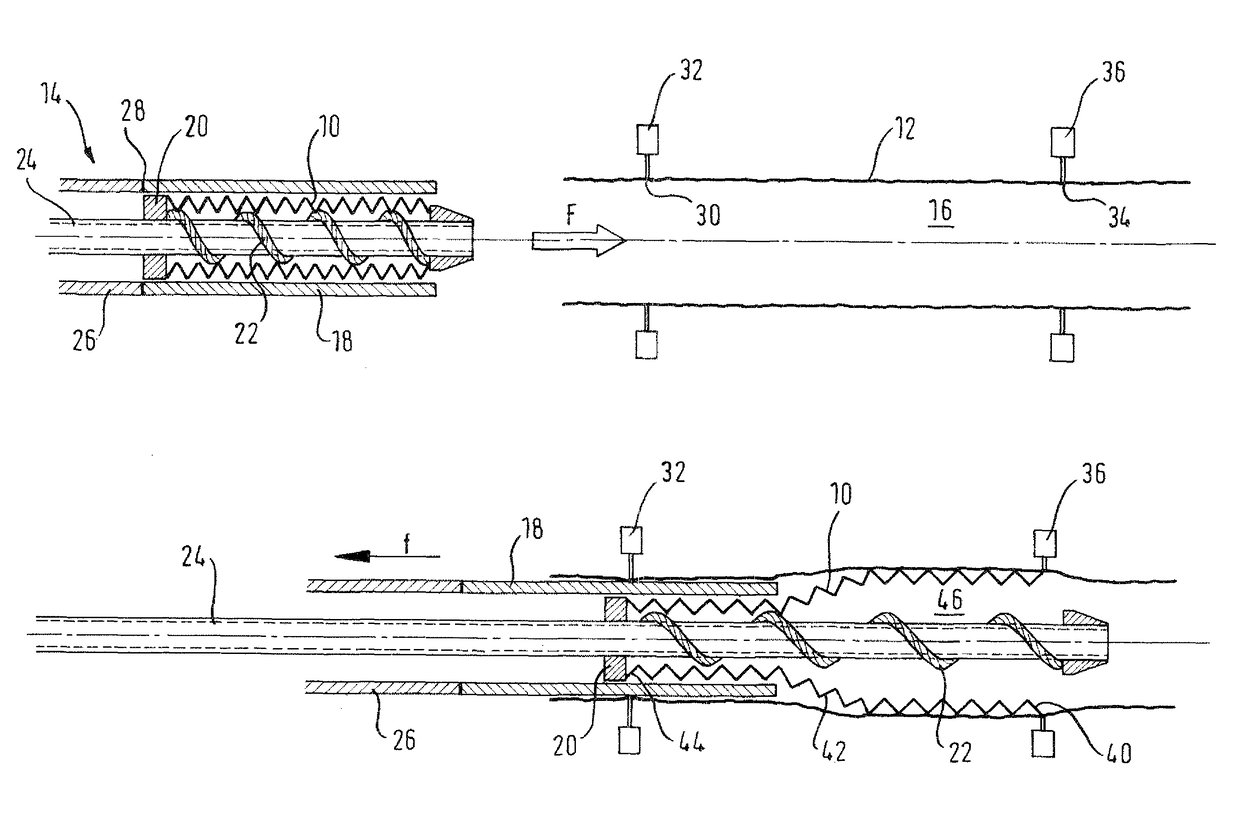
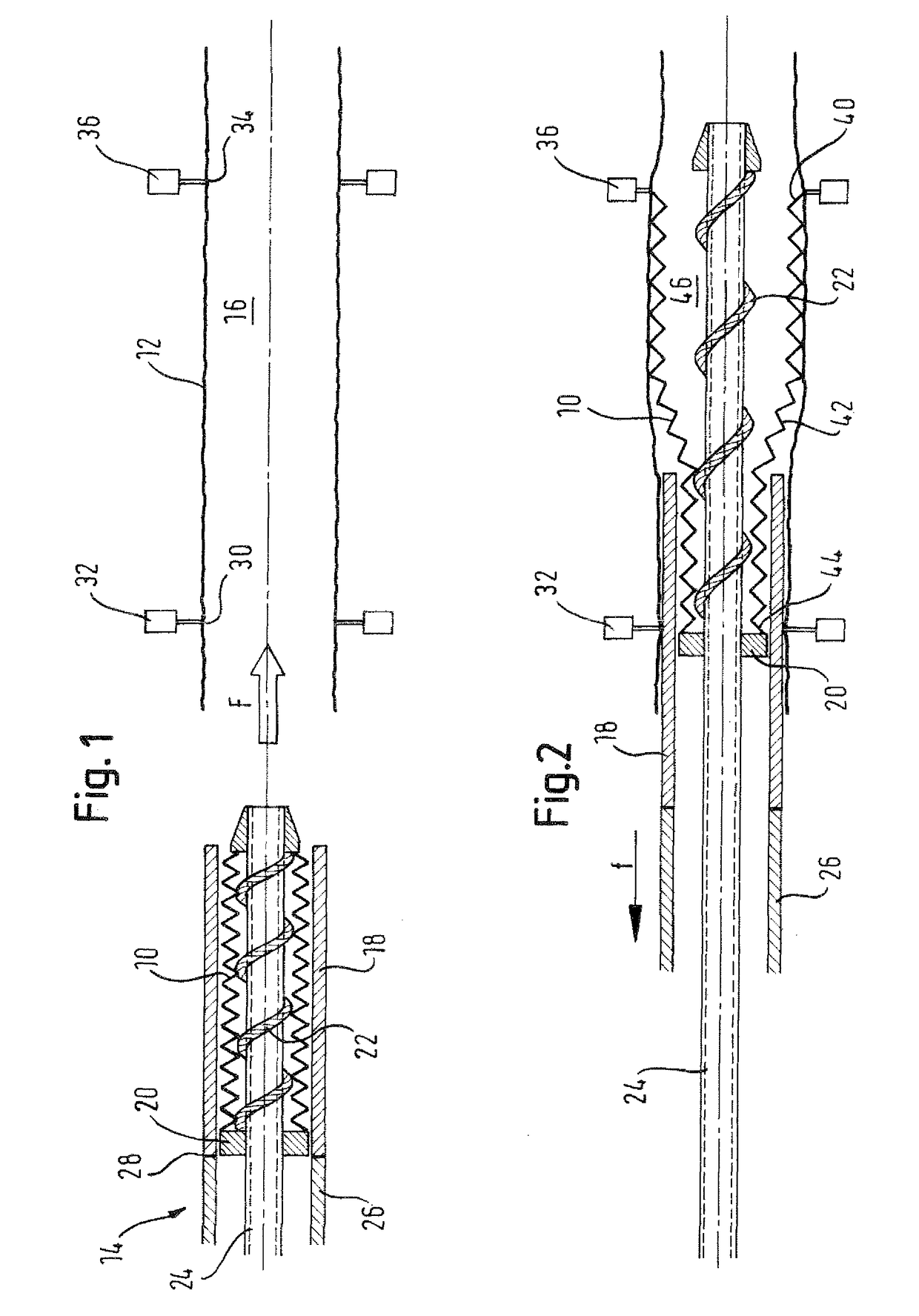
[0063]FIG. 1 shows a crimped covered stent 10 ready for deploying from a loading sheath into a delivery sheath 12, by advancing the stent 10, in a loading tool 14 into the lumen 16 of the sheath 12, in the direction of arrow F.

[0064]The stent 10 is a radially self-expanding nickel titanium alloy stent covered in an ePTFE film. This covered stent is constrained by a loading sheath 18 in a radially compact disposition. The stent is installed in the loading sheath 18 by a “crimping” procedure known per se in which a jig (not shown) compresses the stent radially inwardly, down to its compact disposition, whereupon the stent 10 and the loading sheath 18 are moved relative to each other axially (usually by holding the sheath 18 stationary and translating the stent 10 into the lumen of the sheath 18).

[0065]Before the stent is crimped, there is inserted in its lumen a shaft 24 carrying a sequence of rings standing proud of the cylindrical surface of the shaft, or a spiral thread 22 running ...


PUM


Abstract

There is disclosed herein a method of loading a self-expanding stent (10) into a delivery sheath (12) that is by itself strong enough to preserve the stent in a radially compressed pre-deployment configuration, comprising the steps of: (i) compressing the stent (10) to a relatively small diameter; (ii) providing a loading sheath (18) with an inner diameter d1; (iii) with the stent (10) exhibiting an outside diameter of d2, where d2<d1, providing relative translational movement between the stent (10) and the loading sheath (18), whereby the stent is accommodated within the lumen of the loading sheath (18); (iv) advancing the loading sheath (18), containing the stent (10), into the lumen (16) of the delivery sheath (12); and {v} deploying the stent into the lumen (16) of the delivery sheath (12), by withdrawing the loading sheath (18) while restraining the stent (10) from axial movement out of the lumen (16) of the delivery sheath (12).

Description

PRIORITY[0001]This application is a U.S. national stage application under 35 USC §371 of International Application No. PCT / EP09 / 055592, filed May 8, 2009, claiming the benefit of priority to U.S. Provisional Application No. 61 / 090,772, filed Aug. 21, 2008. This application also claims the priority benefit of U.K. Patent Application No. 0815339.7, filed Aug. 21, 2008 and U.K. Patent Application No. 0808454.3, filed May 9, 2008. Each of which is incorporated by reference into this application as if fully set forth herein.FIELD OF THE INVENTION[0002]This invention relates to a method of loading a self-expanding stent into a delivery sheath that is part of a catheter for transluminal delivery of the stent to a stenting location in the body of a patient, with the stent being deployed at that location by removal from the stent of the constraint on its radial expansion that is provided up to that point by the sheath.[0003]This invention relates to a delivery system for a self-expanding dev...

Claims


Application Information

Patent Timeline
Patent Type & Authority Patents(United States)
IPC IPC(8): A61F2/06A61F2/95A61F2/97
CPCA61F2/95A61F2/97A61F2002/9522A61F2/9522
Inventor DORN, JURGEN
Owner CR BARD INC
Why Eureka
Try Eureka