Delivery system for a self-expanding device for placement in a bodily lumen

a delivery system and self-expanding technology, applied in the field of self-expanding devices for placement in bodily lumens, can solve the problems of small-sized endoprosthesis, uncomplicated procedure, and inability to meet the needs of patients, so as to reduce the risk of damage to the body tissue, facilitate and reliably remove, and simplify the sheath splitting mechanism

Active Publication Date: 2016-07-12
CR BARD INC
View PDF124 Cites 8 Cited by
  • Summary
  • Abstract
  • Description
  • Claims
  • Application Information

AI Technical Summary

Benefits of technology

[0012]A main objective of the invention is to provide a catheter delivery system, where the sheath surrounding the endoprosthesis can be easily and reliably removed. In another objective, the invention aims to provide a catheter delivery system with a simplified sheath splitting mechanism that reduces the risk of damage to the body tissue when the sheath is cut open.
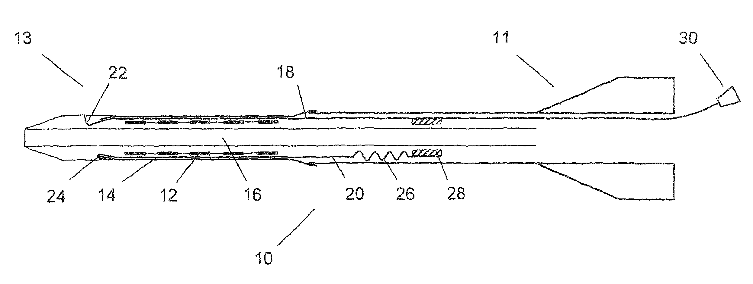
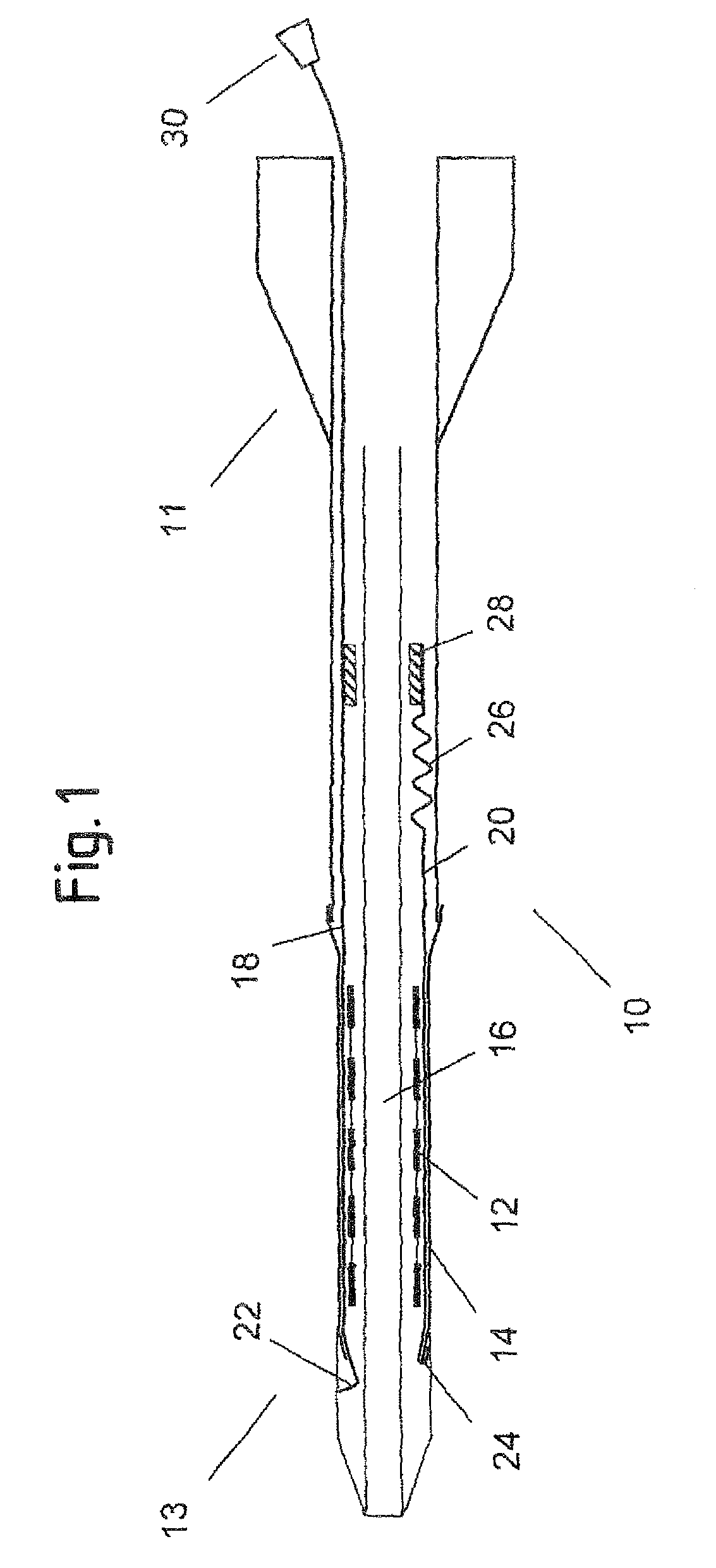
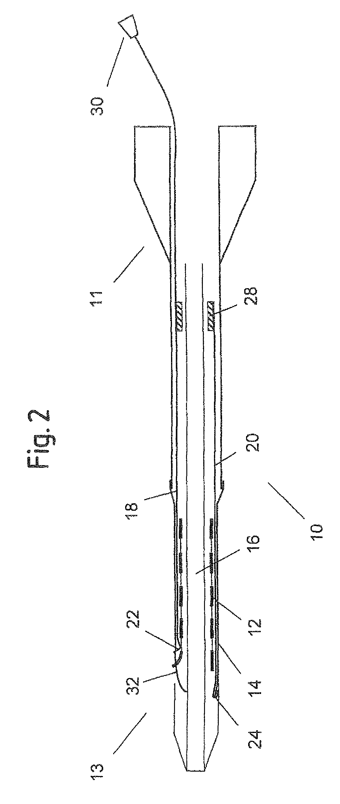
[0013]The invention provides a catheter delivery system for introducing and placing an elongate endoprosthesis in a human or animal body. The catheter delivery system has a proximal end and a distal end and comprises an elongate region at the distal end, in which to receive the endoprosthesis, an elongate sheath to surround the endoprosthesis in the region, and a device for splitting the sheath along its length, to release the endoprosthesis from the region where the endoprosthesis is received. The device for splitting the sheath comprises a first pull element with a proximal end at the proximal end of the delivery system and a distal end, comprising a splitting section for splitting the sheath. The first pull element extends to a distal end of the sheath at a distal end of the delivery system and can be pulled along the length of the sheath from the proximal end of the catheter delivery system. Further, the catheter delivery system comprises a second pull element that pulls the distal end of the sheath proximally during the movement of the first pull element along the length of the sheath. When the first pull element is pulled from the proximal end of the catheter delivery system, the splitting section moves from an original position at the distal end of the sheath towards the proximal catheter delivery system end, thereby splitting the sheath along its length. During this movement of the splitting section, the endoprosthesis expands from a radially compressed state to a radially expanded state in the region where the sheath has already been split. While the splitting section is opening up the sheath, the second pull element pulls the distal sheath end towards the proximal end of the catheter delivery system, thereby removing the sheath from the region where the endoprosthesis has expanded. Once the sheath is fully split, it can be completely removed from the distal end of the catheter delivery system, using the second pull element, and subsequently taken out of the patient's body. The force exerted by the second pull element onto the sheath during the sheath removal process acts on the distal sheath end, so that stretching of the sheath along the pull direction (which may occur when the sheath is pulled from its proximal end) is avoided. Furthermore, when the sheath is starting to be removed, the endoprosthesis has only partly expanded. Thus, the area where the sheath is pushed against the vessel wall by the expanded endoprosthesis is smaller than for the case of a fully expanded endoprosthesis. This leads to a reduction of the frictional forces that have to be overcome in order to move the sheath. Hence, the force required to pull out the sheath is reduced, simplifying the removal process, and the sheath is exposed to a significantly lower level of stress. This is particularly important for the case of thin-walled sheaths, used for deployment of small endoprostheses in narrow blood vessels etc., that may easily stretch or tear, rendering a complete removal impossible or causing undesired movement of the endoprosthesis.
[0014]In a preferred embodiment, the first pull element is a wire. In this way, the pull element can be made with small lateral dimensions, so as to keep a reduced profile of the distal catheter delivery system end and sufficiently stable to avoid deformation or breakage when a pulling force is applied. The wire may have a round radial cross section or may be flattened along a circumferential direction of the endoprosthesis such as to have a ribbon-like shape. In the latter case, lateral movement of the wire along the periphery of the endoprosthesis during the pulling process is reduced and the wire is guided on the abluminal endoprosthesis surface. The splitting section may be attached to the distal end of the wire or may be formed as an integral part thereof. For example, the distal wire end may have a cross section that differs from that of the rest of its length, and that is particularly suited to split the sheath. Furthermore, the distal wire end may stand up in a radial direction of the endoprosthesis or form a hooked portion, so as to reliably catch and split the sheath.

Problems solved by technology

For the case of relatively large endoprostheses, such as oesophagus stents, where sheaths with thick walls can be used, this procedure is normally uncomplicated.
However, problems arise when small-sized endoprostheses are required, for example to widen narrow blood vessels.
When such a thin-walled, cut open sheath is removed from the patient's body by pulling from its proximal end, the friction generated by the abluminal surface of the expanded endoprosthesis and the luminal surface of the vessel may cause either the sheath to tear, inhibiting its complete removal, or the endoprosthesis to move proximally with the sheath being pulled away from the axial position in the bodily lumen where it ought to be.
Similar friction problems may arise even in traditional deployment methods, where an unslitted sheath is withdrawn from the endoprosthesis in the expansion process.
This is particularly important for the case of thin-walled sheaths, used for deployment of small endoprostheses in narrow blood vessels etc., that may easily stretch or tear, rendering a complete removal impossible or causing undesired movement of the endoprosthesis.
This traditional method may cause thin-walled sheaths to stretch or tear, thereby limiting the minimum sheath wall thickness and thus also the minimum achievable distal end profile of the catheter delivery system.
PET is known for its low compliance.
Thus, when said component or portion is moved along the length of the endoprosthesis, it induces extra tension in the sheath which is closely surrounding the endoprosthesis, causing the sheath to tear.

Method used


Image

  • Delivery system for a self-expanding device for placement in a bodily lumen
  • Delivery system for a self-expanding device for placement in a bodily lumen
  • Delivery system for a self-expanding device for placement in a bodily lumen

Examples


Embodiment Construction

[0052]FIG. 1 shows an axial cross section of a catheter delivery system 10 according to a preferred embodiment in an initial position before expansion of the endoprosthesis. The delivery system 10 has a proximal end 11 and a distal end 13, comprising an elongate region 16 where a vascular self-expansible stent 12 is received. The stent 12 is surrounded and held in its radially compressed state by a sheath 14 made of PET. Further, the delivery system 10 comprises a first 18 and a second 20 pull element that both consist of a metallic wire and run between the stent 12 and the sheath 14 in the region 16 where the stent 12 is received. In this region 16, the wires of both pull elements 18, 20 are flattened along a circumferential direction of the stent 12, so as to have a ribbon-like shape. The first pull element 18 has a splitting section 22 at its distal end that is formed by a wire portion standing up in a radial direction of the delivery system 10 and a handle 30 attached to its pro...


PUM


Abstract

A delivery system for a self-expanding device for placement in a bodily lumen, the system comprising a sheath that confines the device to a radially compact delivery disposition until the device is to be released into the lumen, the system having an elongate pull element to be pulled proximally from its proximal end, which pull element is arranged radially inside the sheath for pulling preferentially on a pull zone on the circumference of the distal end of the sheath, thereby to tear the sheath progressively along a tear line running the length of the sheath, starting at the distal end of the sheath, to release the device from the confining effect of the sheath, progressively, beginning at the distal end of the device and wherein the sheath is of polyethylene-terephthalate, cold drawn along its long axis, and in that the distal end of the sheath tapers inwardly to provide an inwardly tapered distal end of the system.

Description

PRIORITY[0001]This application is a U.S. national stage application under 35 USC §371 of International Application No. PCT / EP2008 / 064036, filed Oct. 17, 2008, which claims priority to U.K. Patent Application No. 0720327.6, filed Oct. 17, 2007, and U.K. Patent Application No. 0808454.3, filed May 9, 2008, each of which is incorporated by reference in its entirety into this application.TECHNICAL FIELD[0002]This invention relates to a delivery system for a self-expanding device for placement in a bodily lumen, the system comprising a sheath that confines the device to a radially compact delivery disposition until the device is to be released into the lumen.[0003]The invention also relates to a catheter delivery system for introducing and placing an endoprosthesis in a human or animal body. The catheter delivery system comprises a region in which to receive the endoprosthesis, an elongate sheath to surround the endoprosthesis in the region and a device for splitting the sheath along its...

Claims


Application Information

Patent Timeline
Patent Type & Authority Patents(United States)
IPC IPC(8): A61F2/95A61F2/97
CPCA61F2/95A61F2/97A61F2002/9511A61F2/962A61F2230/0069
Inventor DORN, JURGENHOFFMAN, MARTINATOLLNER, THOMAS
Owner CR BARD INC
Why Eureka
Try Eureka