Device for Regulating the Pressure of Fluids

a fluid pressure and fluid technology, applied in the direction of lift valves, engine components, mechanical apparatus, etc., can solve problems such as friction-related movement energy, and achieve the effect of good suitability

Active Publication Date: 2021-04-29
KAMAT PUMPEN
View PDF0 Cites 0 Cited by
  • Summary
  • Abstract
  • Description
  • Claims
  • Application Information

AI Technical Summary

Benefits of technology

[0018]The device is suitable in particular for use in a high-pressure system with at least 1000 bar, in particular at least 2000 bar. The good suitability for high-pressure applications is due to the fact that owing to the movable mounting of the valve seat, there is no risk of becoming stuck even in the case of very high pressures if an abrupt drop in pressure occurs.

Problems solved by technology

The movability of the valve seat leads to friction-related movement energy during the deflection movement of the valve seat being converted into heat.

Method used


Image

  • Device for Regulating the Pressure of Fluids
  • Device for Regulating the Pressure of Fluids
  • Device for Regulating the Pressure of Fluids

Examples


Embodiment Construction

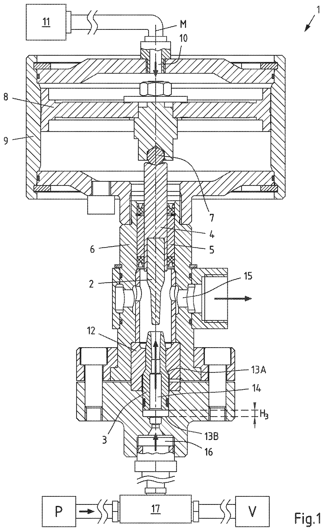
[0024]FIG. 1 shows a device 1 according to the invention for regulating the pressure in a first valve position. The device 1 comprises a closure element 2 designed as a valve plug and a valve seat 3. The closure element 2 and the valve seat 3 are mounted so as to be movable relative to one another and together form a valve, which can be opened and partially or fully closed, i.e. “throttled”. In the position shown in FIG. 1, the closure element 2 and the valve seat 3 are separated from one another, it thus concerns an open valve position. The closure element 2 is connected to a closure element support 4, which is mounted so as to be displaceable in a valve guide 5, which is arranged in a valve housing 6, which has a central axis M. The closure element support 4 is connected via a ball 7 to a piston 8 on the side opposite the closure element 2. The piston 8 is arranged in a cylinder housing 9 connected to the valve housing 6 and is displaceable inside the cylinder housing 9 along the ...


PUM


Abstract

A device (1) is represented and described for regulating the pressure of fluids, comprising: a valve housing (6) with an inlet (16) and with an outlet (15), a closure element (2), which is arranged inside the valve housing (6), and a valve seat (3), which is arranged inside the valve housing (6), wherein the closure element (2) is mounted so as to be movable and wherein the closure element (2) and the valve seat (3) are arranged such that the connection between the inlet (16) and the outlet (15) can be opened and partially or fully closed. In order to prevent the closure element (2) and the valve seat (3) becoming stuck in the case of an abrupt fall in pressure, it is proposed that the valve seat (3) is mounted so as to be movable.

Description

CROSS-REFERENCE TO RELATED APPLICATIONS[0001]This application is the United States national phase of International Application No. PCT / EP2019 / 061185 filed May 2, 2019, and claims priority to German Patent Application No. 10 2018 110 563.0 filed May 3, 2018, the disclosures of which are hereby incorporated by reference in their entirety.BACKGROUND OF THE INVENTIONField of the Invention[0002]The invention relates to a device for regulating the pressure of fluids, comprising: a valve housing with an inlet and with an outlet, a closure element, which is arranged inside the valve housing, a valve seat, which is arranged inside the valve housing, with the closure element being mounted so as to be movable, and with the closure element and the valve seat being arranged such that the connection between the inlet and the outlet can be opened and partially or fully closed.Description of Related Art[0003]In the case of many applications, it is required to regulate the pressure of fluids and for...

Claims


Application Information

Patent Timeline
Patent Type & Authority Applications(United States)
IPC IPC(8): F16K1/42F16K1/36F16K1/44
CPCF16K1/42F16K1/44F16K1/36
Inventor CHENGOUR, MOHAMMED
Owner KAMAT PUMPEN
Why Eureka
Try Eureka