Zoom lens and imaging apparatus

a technology of zoom lens and imaging apparatus, applied in the field of zoom lens, can solve the problems of insufficient performance of zoom lens with respect to correcting aberrations and suppressing so as to achieve small aberration fluctuations during focusing operations, favorable correction of various aberrations, and high image quality

Active Publication Date: 2017-08-01
FUJIFILM CORP
View PDF6 Cites 2 Cited by
  • Summary
  • Abstract
  • Description
  • Claims
  • Application Information

AI Technical Summary

Benefits of technology

The present invention provides a high performance zoom lens that is compatible with the increased number of pixels in digital cameras and can favorably correct various aberrations while exhibiting small fluctuations in aberrations during focusing operations. The zoom lens consists of five lens groups, which have specific shapes and distances between them. The first lens group has a positive refractive power, the second lens group has a negative refractive power, the third lens group has a positive refractive power, the fourth lens group has a negative refractive power, and the fifth lens group has a positive refractive power. The zoom lens has a small F value throughout the entire zoom range, favorably corrects various aberrations, and exhibits small fluctuations in aberrations during focusing operations. The imaging apparatus equipped with this zoom lens can obtain images which are bright and have high image quality.

Problems solved by technology

However, the zoom lenses of Japanese Unexamined Patent Publication Nos. 2003-287681, 61(1986)-286813 and 2014-102526 have large F values at the telephoto end, and it also cannot be said that the performance thereof with respect to correcting aberrations and suppressing fluctuations in aberrations during focusing operations is sufficiently high.
In addition, although the zoom lens of Japanese Unexamined Patent Publication No. 2013-182246 has a small F value throughout the entire zoom range, it cannot be said that the performance thereof with respect to correcting aberrations and suppressing fluctuations in aberrations during focusing operations is sufficiently high.

Method used


Image

  • Zoom lens and imaging apparatus
  • Zoom lens and imaging apparatus
  • Zoom lens and imaging apparatus

Examples


Embodiment Construction

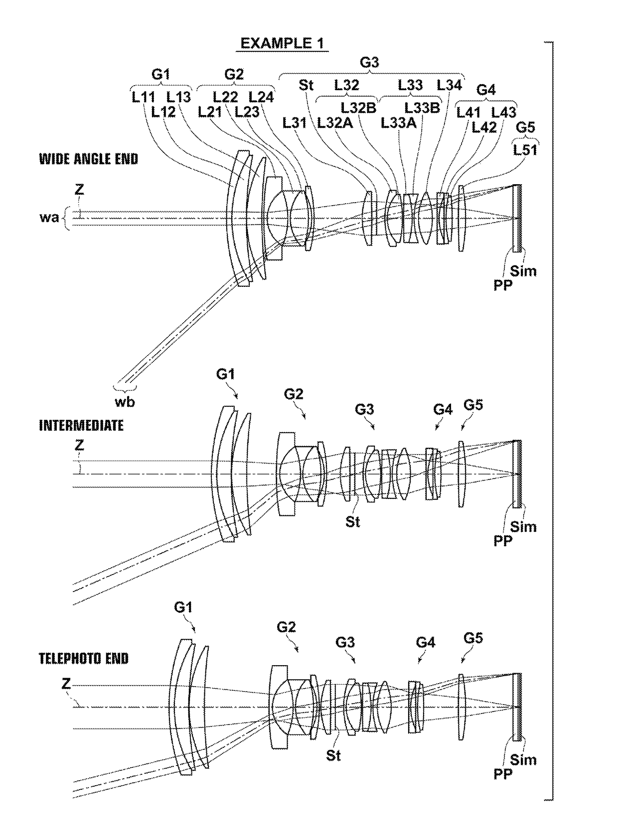
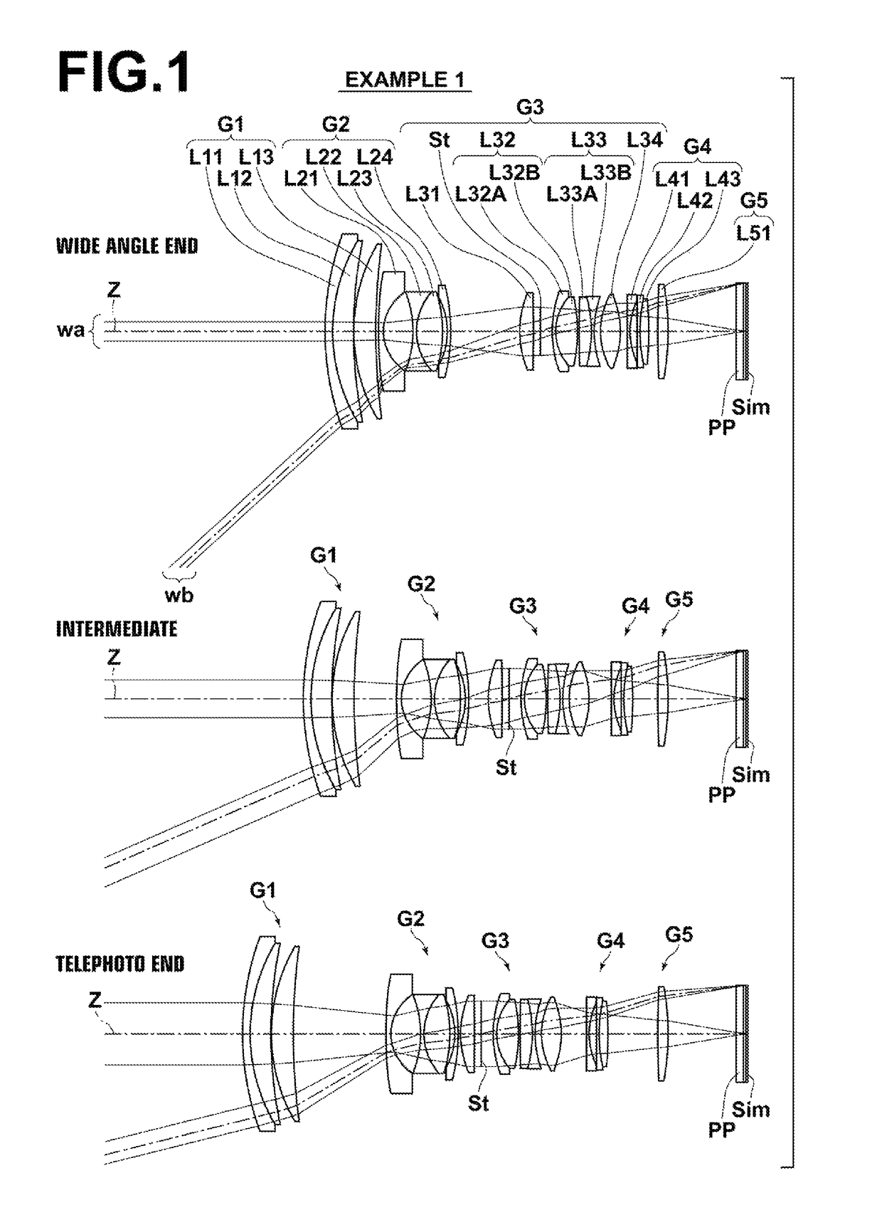
[0057]Hereinafter, embodiments of the present disclosure will be described in detail with reference to the attached drawings. FIG. 1 is a collection of sectional diagrams that illustrate the configuration of a zoom lens according to an embodiment of the present disclosure, and FIG. 6 is a diagram that illustrates the trajectories of movement when changing magnification in this zoom lens. The example of the configuration illustrated in FIG. 1 is the same as the configuration of a zoom lens of Example 1 to be described later. In addition, the movement trajectories illustrated in FIG. 6 are common to those of the configurations of zoom lenses of Examples 1 through 5 to be described later. In FIG. 1, the left side is the object side and the right side is the image side. The aperture stop St illustrated in FIG. 1 does not necessarily represent the size or shape thereof, but the position of the aperture stop St along an optical axis Z. In addition, FIG. 1 illustrates an axial light beam w...


PUM


Abstract

A zoom lens includes, in order from the object side: a positive first lens group; a negative second lens group; a positive third lens group; a negative fourth lens group; and a positive fifth lens group. The distance between the first and second lens groups constantly increases, the distance between the second and third lens groups constantly decreases, the distance between the third and fourth lens groups constantly changes, and the distance between the fourth and fifth lens groups constantly increases when changing magnification from the wide angle to the telephoto end. The first lens group includes, in order from the object side, a negative lens, a positive lens, and a positive lens. The fourth lens group includes, in order from the object side, a negative lens, a negative lens, and a positive lens, and moves toward the image side when focusing from a far distance to a close distance.

Description

CROSS REFERENCE TO RELATED APPLICATIONS[0001]The present application claims priority under 35 U.S.C. §119 to Japanese Patent Application No. 2014-243846 filed on Dec. 2, 2014. The above application is hereby expressly incorporated by reference, in its entirety, into the present application.BACKGROUND[0002]The present disclosure is related to a zoom lens which is particularly favorably suited for use in digital cameras, interchangeable lens digital cameras, and cinematic cameras. The present disclosure is also related to an imaging apparatus equipped with the zoom lens.[0003]Zoom lenses having five group configurations for use in digital cameras, interchangeable lens digital cameras, and cinematic cameras are known, as disclosed in Japanese Unexamined Patent Publication Nos. 2003-287681, 61(1986)-286813, 2014-102526 and 2013-182246.SUMMARY[0004]Recently, the number of pixels in digital cameras, interchangeable lens digital cameras, and cinematic cameras is increasing. Therefore, ther...

Claims


Application Information

Patent Timeline
Patent Type & Authority Patents(United States)
IPC IPC(8): G02B15/14G02B15/20G02B15/163G02B27/00
CPCG02B15/20G02B15/163G02B27/0025G02B15/173G02B15/145121
Inventor NODA, TAIGACHO, MICHIO
Owner FUJIFILM CORP
Why Eureka
Try Eureka