
Hierarchical distributed antenna system

a distributed antenna and distributed antenna technology, applied in the field of wireless communication system, can solve the problems of limiting the quality of mobile communication service, vendors are reluctant to implement this kind of large antenna array, and the design and aerodynamics of vehicles, so as to achieve the effect of significantly reducing the overhead of signaling between cu and du and reducing the cost of implementation

Active Publication Date: 2017-08-01
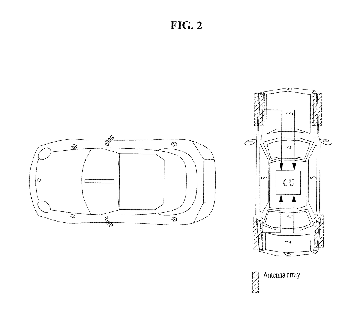
LG ELECTRONICS INC
View PDF5 Cites 0 Cited by
  • Summary
  • Abstract
  • Description
  • Claims
  • Application Information

AI Technical Summary

Benefits of technology

The invention reduces the signaling between certain parts of a communication system, making it more efficient and cost-effective. This can make the system easier to implement and use.

Problems solved by technology

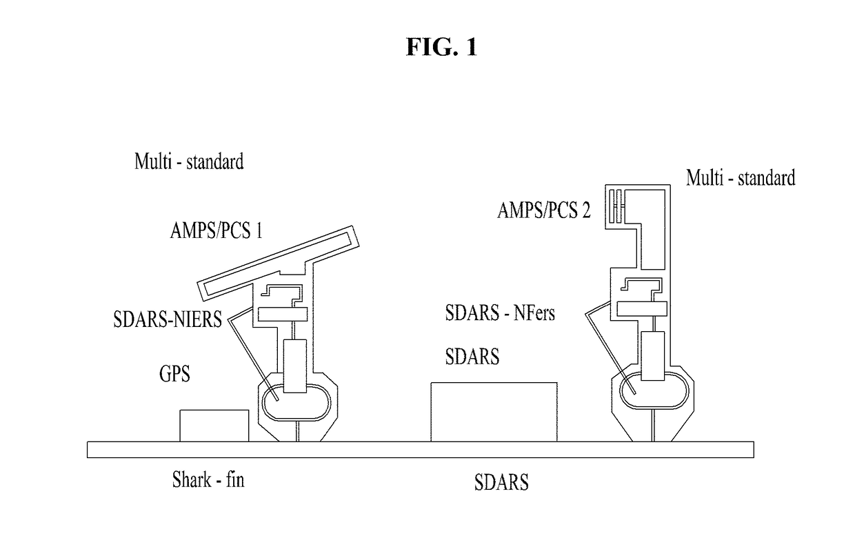
However, implementing the large size antenna array in the outside of vehicle has drawback for vehicle design and for aerodynamics.
So, the vehicle vendors are reluctant to implement this kind of large antenna array.
So, it has limit for providing high quality mobile communication service.
Large sized antennas would not good for car design and reduce the original driving performance of the vehicle.

Method used


Image

  • Hierarchical distributed antenna system
  • Hierarchical distributed antenna system
  • Hierarchical distributed antenna system

Examples


first embodiment

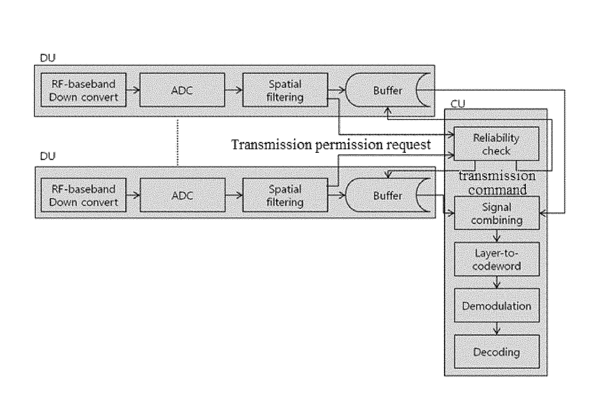
[0083]The first embodiment proposes that each DU transmit information about reliability of each reception unit, such as a layer or a transport block, to a CU and the CU compare reliability of each reception unit to determine a reception unit that a DU is to transmit to the CU.

[0084]In the structure of FIG. 7, each of DUs first transmits a transmission permission request signal to a CU before transmitting a quantized digital value to the CU. This is to control cable traffic at a proper level or implement a DAS receiver using a capability limited cable by causing the CU to first determine reliability of each reception unit with respect to each DU and transmit, to the CU, only a signal received with high reliability which is worth transmitting to the CU through a cable.

[0085]FIG. 8 shows an example for reducing internal signaling overhead between DUs and CU.

[0086]Specifically, FIG. 8 shows that transmission control described above is helpful to DAS implementation through a low capacity...

second embodiment

[0097]The second embodiment proposes a scheme in which each DU first transmits some information needed to restore data to a CU and the CU determines reception reliability of each DU based on the information and selects information (e.g., a codeword or a layer) that each DU is to transmit to the CU.

[0098]In the examples of FIG. 7 and FIG. 9, upon transmitting the transmission permission request signal to the CU, each DU transmits information capable of determining reliability of a signal received thereby in the transmission permission request signal. As the amount of information about a reception signal that the DU transmits to the CU or the amount of information about reliability of the reception signal increases, the CU may accurately determine reliability of each signal received by each DU but transmission of excessive information causes increase in cable traffic.

[0099]To avoid such a disadvantage, the present invention proposes a scheme of using some of signals that the DU should...


PUM


Abstract

The present document is for a wireless communication with reduced internal signaling burden in the distributed antenna system (DAS). In the proposed method, a user equipment (UE) receives signals, from the network, by multiple distributed unit (DUs) distributed within the UE, wherein the multiple DUs comprise one or more main DUs and one or more sub DUs; reports, by the sub DUs, first reception information of the signals to one of the main DUs; reports, by the one of the main DUs, second reception information of the signals to a central unit (CU) controlling the multiple DUs based on the first reception information of the signals; and determines, at the CU, which one or more DUs among the multiple DUs are to transfer the received signals to the CU based on the second reception information of the signals.

Description

CROSS REFERENCE[0001]This application claims the benefit of the U.S. Provisional Patent Application No. 62 / 163,965, filed on May 19, 2015, which is hereby incorporated by reference as if fully set forth herein.BACKGROUND OF THE INVENTION[0002]Technical Field[0003]The present document is for a wireless communication system. More particularly, the present document is for a wireless communication with reduced internal signaling burden in the distributed antenna system (DAS) by applying hierarchical structure.[0004]While the present document mainly discuss this with the example of implementing in-vehicle DAS system, it is only exemplary, and the proposed scheme / structure can be used for simple configuration of MIMO system with DAS configuration.[0005]Discussion of the Related Art[0006]In the conventional mobile communication system for mainly serving personal mobile communication devices, there is an inverse proportional relationship between the speed of the UE and required data rate / Qo...

Claims


Application Information

Patent Timeline
Patent Type & Authority Patents(United States)
IPC IPC(8): G06F17/00H04B7/08H01Q21/28H01Q1/32H04W88/06
CPCH04B7/0808H01Q21/28H01Q1/3275H04W88/06H04B7/0404H04B7/0874
Inventor PARK, KYUNGMINKANG, JIWONKIM, KITAELEE, KILBOMKIM, HEEJIN
Owner LG ELECTRONICS INC
Learn More