AI technical title is built by PatSnap AI team. It summarizes the technical point description of the patent document.
a superconducting cable and terminal unit technology, applied in the direction of cable fittings for cryogenic cables, coupling contact members, coupling device connections, etc., can solve the problems of additional measures and costs, difficult management of external electrical fields, etc., and achieve the effect of convenient and safe access for operating personnel
Active Publication Date: 2017-08-15
NEXANS
View PDF5 Cites 0 Cited by
Summary
Abstract
Description
Claims
Application Information
AI Technical Summary
This helps you quickly interpret patents by identifying the three key elements:
Problems solved by technology
Method used
Benefits of technology
Benefits of technology
[0009]The object of the present invention is to provide a compact and simple termination unit which allows an easy and safe access for the operating personnel.
[0013]In some embodiments, the grounded casing comprises a plurality of casing segments, each casing segment comprising one of the bushings, and each casing segment being associated with one phase of the cable, wherein the casing segments are electrically connected to each other. Such a casing allows for an easy assembly of the termination unit.
[0015]Advantageously, each bushing comprises an electrical field management component. This allows for avoiding critical electrical field concentrations at the end of each phase conductor.
[0018]In some embodiments, the second electrical connector is a plug connector. Such a connector allows for easy assembling of the unit. Alternatively, the second electrical connector is made of flexible conductive elements. For example, the second electrical connector may be made of a copper wire mesh. Flexible conductive elements may compensate for deformation due to possible temperature differences between the internal envelope and the casing.
Problems solved by technology
However, such a termination design implies external electrical fields present at the outside of the termination unit.
These external electrical fields are difficult to manage if the termination unit is to be used, for example, in a substation.
Indeed, in this case, additional measures and costs have to be engaged in order to ensure the security of the operator.
Method used
Image
Click on the blue label to locate the original text in one second.
Reading with bidirectional positioning of images and text.
Examples
Embodiment Construction
[0026]The figures and the following description illustrate exemplary embodiments. In the figures, elements with similar structures and / or functions may be denoted by like reference numerals. In the following described embodiments of the invention, the superconducting cable is a three-phase cable.
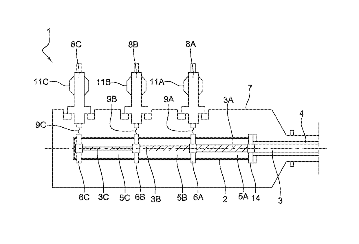
[0027]FIG. 1 schematically shows an embodiment of the termination unit 1 according to the present disclosure. The termination unit 1 comprises an internal envelope 2 containing the end of the superconducting cable 3 and a cryogenic fluid. The three phase conductors 3A, 3B, 3C of the cable 3 are arranged concentrically and are bared within the internal envelope such that each phase conductor 3A, 3B, 3C has a contacting surface extending longitudinally and being exposed to the cryogenic fluid. The inner cryogenic envelope 4 of the cable 3 is connected to the internal envelope 2 and tightly sealed to it by means of a cryogenic flange 14.
[0028]The internal envelope 2 is made of an electrically i...
PUM
Abstract
A termination unit (1) for a superconducting cable (3), has an internal electrically insulating envelope (2) containing the phase conductors (3A, 3B, 3C) of the cable (3) in a cryogenic fluid. The internal envelope (2) has, for each phase conductor (3A, 3B, 3C), one first electrical connector (6A, 6B, 6C) connected to the corresponding phase conductor (3A, 3B, 3C) and protruding from the internal envelope (2). The termination unit (1) further has an electrically conductive, grounded casing (7) surrounding the internal envelope (2) and the first electrical connectors (6A, 6B, 6C), the grounded casing (7) comprising one bushing (8A, 8B, 8C) for each one of the first electrical connectors (6A, 6B, 6C), each bushing (8A, 8B, 8C) being connected to one of the first electrical connectors (6A, 6B, 6C) by a second electrical connector (9A, 9B, 9C) and being adapted to transmit voltage and current from its associated phase conductor (3A, 3B, 3C).
Description
RELATED APPLICATION[0001]This application claims the benefit of priority from European Patent Application No. 15 305 338.4, filed on Mar. 5, 2015, the entirety of which is incorporated by reference.BACKGROUND[0002]Field of the Invention[0003]The invention concerns a termination unit for a single- or multiphase superconducting cable.[0004]Description of the Related Art[0005]Single- or multiphase superconducting cables consist: of one or N concentrically arranged superconducting phase conductor(s) and an external neutral or screen conductor around a tubular or massive supporting core extending along a longitudinal axis, whereby all the superconducting phases as well as the outermost superconducting phase and the neutral conductor are separated from each other by an insulating layer. Each superconducting phase conductor may consist of multiple layers of superconducting wires or tapes, wherein an electrical insulation might be present in between the layers of one phase conductor. The ca...
Claims
Application Information
Patent Timeline
Application Date:The date an application was filed.
Publication Date:The date a patent or application was officially published.
First Publication Date:The earliest publication date of a patent with the same application number.
Issue Date:Publication date of the patent grant document.
PCT Entry Date:The Entry date of PCT National Phase.
Estimated Expiry Date:The statutory expiry date of a patent right according to the Patent Law, and it is the longest term of protection that the patent right can achieve without the termination of the patent right due to other reasons(Term extension factor has been taken into account ).
Invalid Date:Actual expiry date is based on effective date or publication date of legal transaction data of invalid patent.

