Push-pull type fiber optic connector assembly

a fiber optic connector and push-pull technology, applied in the field of push-pull fiber optic connector assembly, can solve the problems of inconvenient finger access and unsatisfactory use of this design of supplementary tools, and achieve the effect of convenient single-hand operation and less effor

Active Publication Date: 2017-08-22
CORNING OPTICAL COMM LLC
View PDF21 Cites 27 Cited by
  • Summary
  • Abstract
  • Description
  • Claims
  • Application Information

AI Technical Summary

Benefits of technology

[0010]The present invention has been accomplished under the circumstances in view. It is therefore the main object of the present invention to provide a push-pull type fiber optic connector assembly, which comprises a fiber optic connector and an operating handle. The fiber optic connector is connectable to a fiber optic adapter, comprising a connector housing, a latch having an elastic arm backwardly extended from the top of the connector housing for locking the connector housing to the fiber optic adapter, a recessed portion located at a rear bottom side relative to the latch, a wedge-shaped pressure rod backwardly extended from the recessed portion, a fiber ferrule mounted in a cable passage inside the connector housing, a connector sub assembly mounted in the connector housing to hold the fiber ferrule in place, and a fiber optic cable having a fiber core inserted through the fiber ferrule. The operating handle comprises a sliding cap movably capped on the connector housing, a push member having a push arm forwardly extended from the sliding cap, a cam located at one lateral side of a distal end of the push arm and inserted into the recessed portion of the fiber optic connector, and a handle shaft backwardly extended from the sliding cap and operable to pull the sliding cap backwards in forcing down the wedge-shaped pressure rod for disengaging the fiber optic connector from the fiber optic adapter. Because the operating handle pulling direction is the same as the direction of withdrawing the fiber optic connector out of the fiber optic adapter, this single-action operation is ergonomically in conformity with natural gestures, and thus, the invention achieves convenient single-hand operation with less effort.
[0011]According to still another aspect of the present invention, the connector sub assembly comprises a front mating receptacle connected to the connector housing, a rear hollow connection axially backwardly extended from the front mating receptacle and coupled with the outer jacket of the fiber optic cable, and a stop block located at the top side of the front mating receptacle adjacent to the rear hollow connection. The operating handle further comprises an opening located at a front side of the rectangular sliding cap, a receptacle chamber defined in the rectangular sliding cap between two opposite side panels of the rectangular sliding cap in communication with the opening, a position-limit slot located in the top wall of the sliding cap in communication with the receptacle chamber for receiving the stop block of the connector sub assembly. When pulling the operating handle, the stop block of the connector sub assembly is moved in the position-limit slot and then stopped at the front side of the position-limit slot, preventing disconnection of the operating handle from the fiber optic connector to cause function failure or structural damage.
[0012]According to still another aspect of the present invention, the operating handle comprises the opening located at a front side of the rectangular sliding cap, the receptacle chamber defined in the rectangular sliding cap between two opposite side panels of the rectangular sliding cap in communication with the opening, and two slits respectively located at the two side panels of the rectangular sliding cap and longitudinally extended to the opening. Subject to the effect of the slits, the opposing top and bottom walls of the sliding cap of the operating handle can be forced vertically outwards by the connector sub assembly for enabling the stop block of the connector sub assembly to be moved into the position-limit slot in the top wall of the sliding cap of the operating handle, simplifying the installation of the push-pull type fiber optic connector assembly, enhancing structural stability, facilitating installation and increasing the production efficiency.
[0013]According to still another aspect of the present invention, the wedge-shaped pressure rod of the latch of the fiber optic connector has a width about ½ of the width of the elastic arm. Further, the push arm extends forwardly from the sliding cap in an offset manner relative to the wedge-shaped pressure rod of the latch. The push member of the operating handle further comprises a shoulder forwardly extended from one lateral side of the push arm, and a gap defined between the shoulder and the push arm for receiving the wedge-shaped pressure rod of the latch. The design of the shoulder prevents the wedge-shaped pressure rod of the latch from being pressed accidentally to unlock the latch of the fiber optic connector from the fiber optic adapter.

Problems solved by technology

Further, in actual application it is quite inconvenient to access the fingers to the press plate A31 of the fiber optic connector A in a fiber optic connector array, complicating fiber optic connector mounting and dismounting operations.
Thus, the use of this design of supplementary tool is still not satisfactory.

Method used


Image

  • Push-pull type fiber optic connector assembly
  • Push-pull type fiber optic connector assembly
  • Push-pull type fiber optic connector assembly

Examples


Embodiment Construction

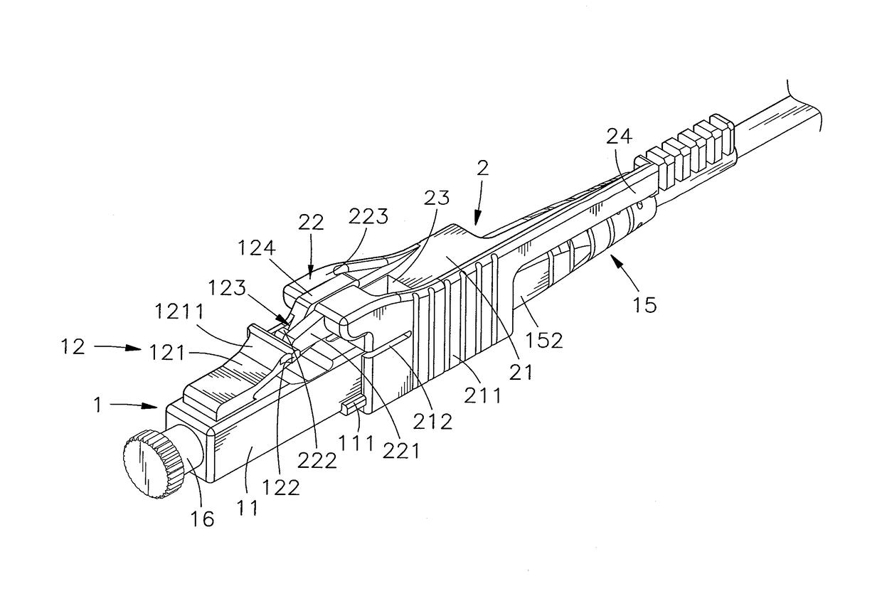
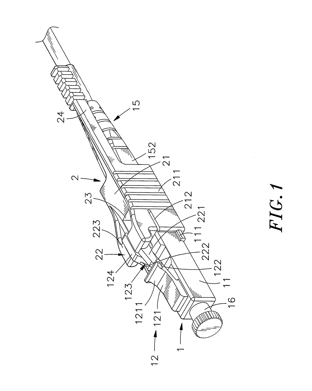
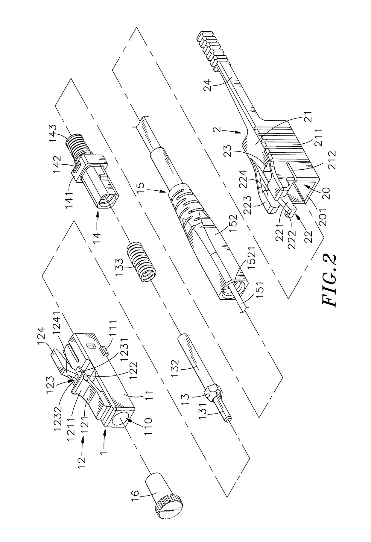
[0027]Referring to FIGS. 1-4, a push-pull type fiber optic connector assembly in accordance with the present invention is shown. The push-pull type fiber optic connector assembly comprises a fiber optic connector 1 and an operating handle 2.

[0028]The fiber optic connector 1 comprises a rectangular connector housing 11, a latch 12 suspending at a top side of the connector housing 11, a fiber ferrule 13, a connector sub assembly 14, and a fiber optic cable 15.

[0029]The latch 12 comprises an elastic arm 121 having an upwardly backward sloping top guide surface 1211, two coupling blocks 122 respectively protruded from two opposite lateral sides of the elastic arm 121, a recessed portion 123 located at a rear side of the top guide surface 1211, a wedge-shaped pressure rod 124 of width about ½ of the width of the elastic arm 121 backwardly extended from the recessed portion 123 and suspending above the elevation of the coupling blocks 122, a connection plate 1231 located at a bottom side ...


PUM


Abstract

A push-pull type fiber optic connector assembly includes a fiber optic connector connectable to fiber optic adapter and including connector housing, latch having elastic arm extended from top of connector housing for locking connector housing to fiber optic adapter, recessed portion located at bottom side relative to latch, pressure rod extended from recessed portion, fiber ferrule mounted in cable passage inside connector housing, connector sub assembly mounted in connector housing to hold fiber ferrule and fiber optic cable having fiber core inserted through fiber ferrule, and operating handle including sliding cap movably capped on connector housing, push member having push arm forwardly extended from sliding cap, cam located at one side of push arm and inserted into recessed portion of fiber optic connector, and handle shaft extended from sliding cap to pull sliding cap backwards in forcing down wedge-shaped pressure rod for disengaging fiber optic connector from fiber optic adapter.

Description

REFERENCE TO RELATED APPLICATIONS[0001]This Patent Application is based on Provisional Patent Application Ser. No. 62 / 179,394, filed 7 May 2015, currently pending.BACKGROUND OF THE INVENTION[0002]1. Field of the Invention[0003]The present invention relates to electrical connector technology and more particularly, to a push-pull fiber optic connector assembly, which comprises a fiber optic connector holding the fiber core of a fiber optic cable in a fiber ferrule inside a connector housing and having a latch for locking the connector housing to a fiber optic adapter, and an operating handle having a sliding cap located at the front side and coupled to the connector housing and a push member for biasing the latch to unlock the connector housing of the fiber optic connector from the fiber optic adapter when the user pulls the handle shaft of the operating handle backwards.[0004]2. Description of the Related Art[0005]With rapid development of modern communications technology and the Int...

Claims


Application Information

Patent Timeline
Patent Type & Authority Patents(United States)
IPC IPC(8): G02B6/38
CPCG02B6/3893G02B6/3821G02B6/3825G02B6/3898G02B6/3869
Inventor LEE, JHIH-PING
Owner CORNING OPTICAL COMM LLC
Why Eureka
Try Eureka