Supercharge Your Innovation With Domain-Expert AI Agents!

Module or arrangement for, and method of, uniformly and efficiently illuminating a target by generating an illumination pattern that is substantially congruent to and overlaps a field of view of an imaging reader

a module or arrangement and illumination pattern technology, applied in the field of modules or arrangements for, and a method of, illuminating targets, can solve the problems of not always achieving uniform and/or efficient illumination of targets over a broad range of working distances, and low illumination light delivered to each targ

Active Publication Date: 2017-08-22
SYMBOL TECH LLC
View PDF3 Cites 2 Cited by
  • Summary
  • Abstract
  • Description
  • Claims
  • Application Information

AI Technical Summary

Benefits of technology

The present invention relates to an improved method of illuminating a target for electro-optical reading by image capture. The invention aims to generate an illumination light pattern that is congruent with the field of view of the imaging reader and efficiently transmits illumination light to the target. The current method of illumination, which involves a separate light source and imager, results in non-uniform and low-efficient lighting of the target. The invention proposes a compound parabolic reflector (CPR) that can be used to generate a uniform and efficient illumination light pattern that matches the field of view of the imaging reader. The CPR is a special optical device that can be integrated into the imaging reader to capture the target and efficiently transmit the illumination light to the target. The technical effect of the invention is to improve the uniformity and efficiency of illumination for electro-optical reading by generating an illumination light pattern that matches the field of view of the imaging reader.

Problems solved by technology

Although generally satisfactory for its intended purpose, the illumination light does not always uniformly and / or efficiently illuminate the targets over a broad range of working distances relative to the reader.
In the prior art, however, this is not always achieved, primarily because the illumination light source and the imager are physically spaced apart and are horizontally and / or vertically offset from each other.
Also, the typical illumination light pattern is mismatched, i.e., not substantially congruent, to the field of view, and the amount of illumination light delivered to each target is low, thereby resulting in a poor light transmission efficiency.

Method used


Image

  • Module or arrangement for, and method of, uniformly and efficiently illuminating a target by generating an illumination pattern that is substantially congruent to and overlaps a field of view of an imaging reader
  • Module or arrangement for, and method of, uniformly and efficiently illuminating a target by generating an illumination pattern that is substantially congruent to and overlaps a field of view of an imaging reader
  • Module or arrangement for, and method of, uniformly and efficiently illuminating a target by generating an illumination pattern that is substantially congruent to and overlaps a field of view of an imaging reader

Examples


Embodiment Construction

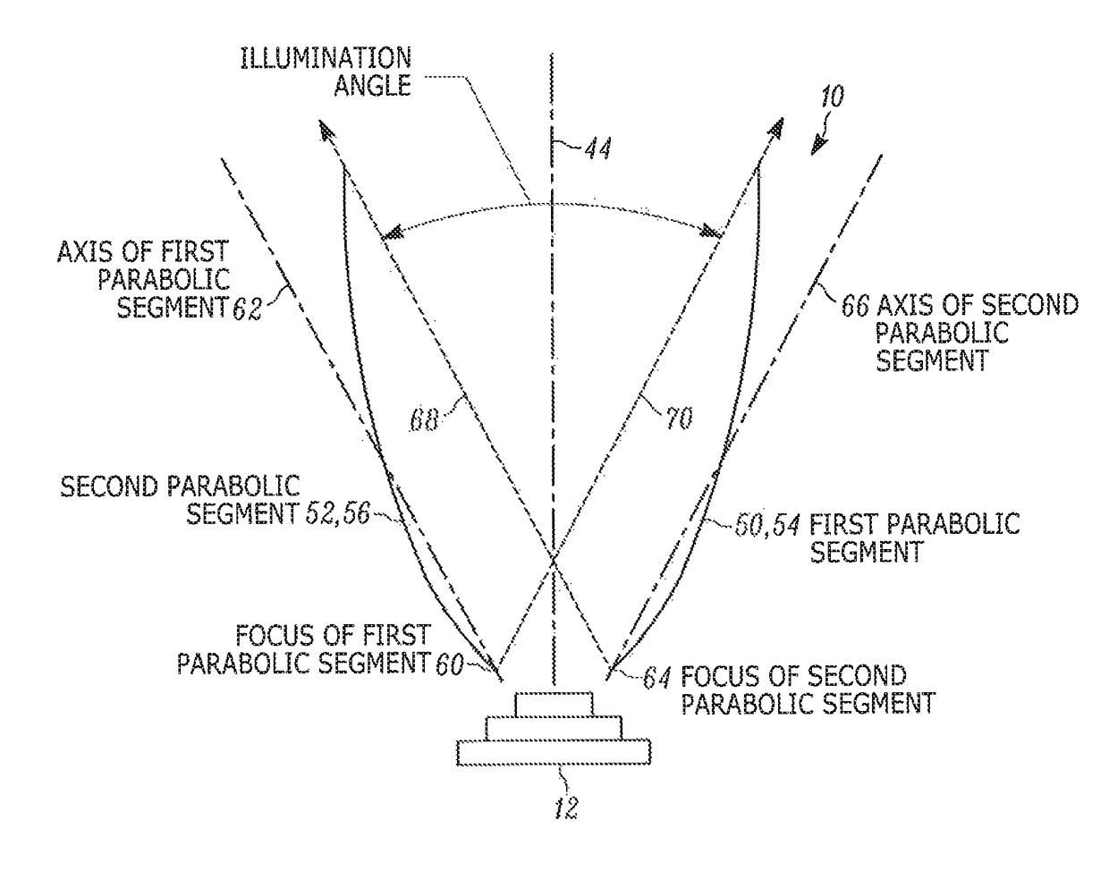
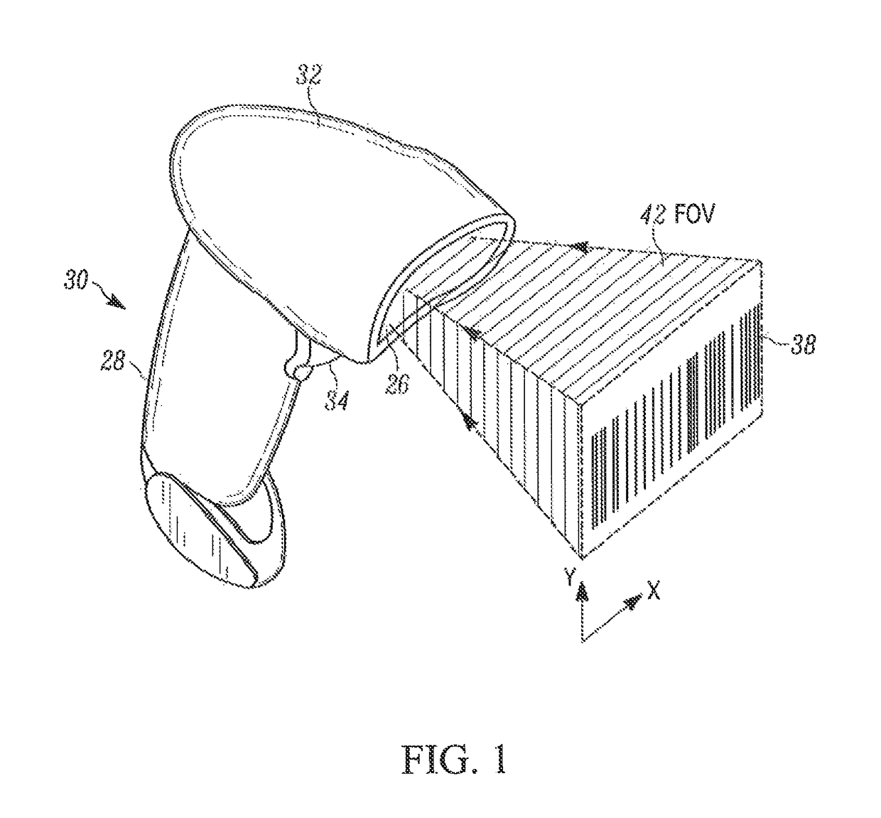
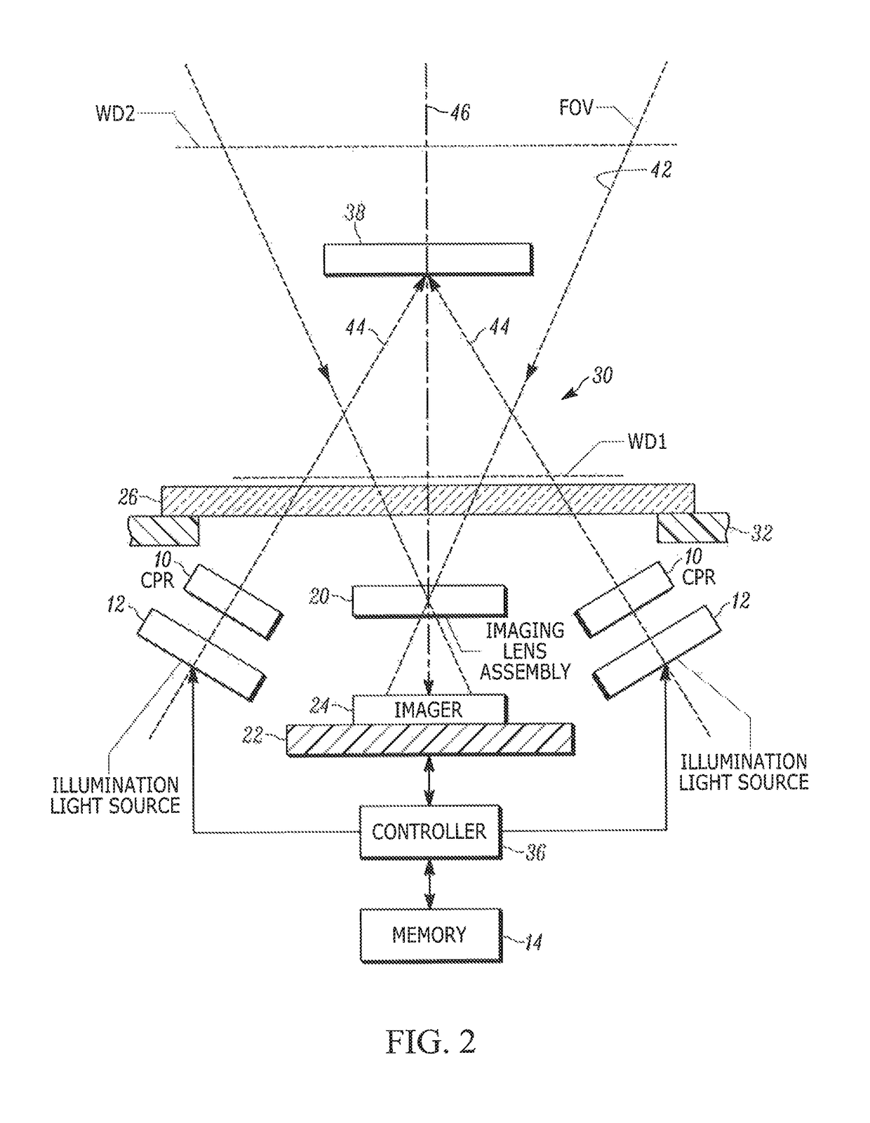
[0018]In accordance with one feature of this disclosure, an imaging module illuminates a target to be read by image capture, where the target is preferably a bar code symbol that is generally rectangular in shape. The imaging module includes an illumination light source, e.g., one or more light emitting diodes (LEDs), for emitting illumination light toward the target for reflection and scattering therefrom, and an imaging assembly having a two-dimensional array of image sensors for capturing the illumination light returning from the target along an imaging axis over a field of view, preferably likewise of generally rectangular shape, that extends along first and second extents, preferably of different extents, along mutually orthogonal, first and second directions that are generally perpendicular to the imaging axis. Typically, each one or more of the LEDs is offset, and spaced away from, the array along the first direction and / or the second direction. The imaging module also includ...


PUM


Abstract

An illumination light source emits illumination light toward a target to be read by image capture. An imaging assembly captures the illumination light returning from the target along an imaging axis over a field of view that extends along mutually orthogonal, first and second directions that are generally perpendicular to the imaging axis. A compound parabolic reflector receives, and optically modifies, the emitted illumination light to generate a generally uniform illumination light pattern that is substantially congruent to, and substantially overlaps, the field of view along both of the first and second directions. The compound parabolic reflector has first and second pairs of parabolic segments for respectively reflecting the emitted illumination light over first and second illumination angles along the first and second directions.

Description

BACKGROUND OF THE INVENTION[0001]The present disclosure relates generally to a module or arrangement for, and a method of, illuminating a target to be electro-optically read by image capture and, more particularly, to uniformly and efficiently illuminate the target by generating an illumination light pattern that is substantially congruent to, and substantially overlaps, a field of view of an imaging reader.[0002]Solid-state imaging systems or imaging readers have long been used, in both handheld and hands-free modes of operation, in many industries, such as retail, manufacturing, warehousing, distribution, postal, transportation, logistics, etc., to electro-optically read targets, such as one- or two-dimensional bar code symbols to be decoded. A known imaging reader generally includes an imaging module that is mounted in a housing, and that has an illumination light source for emitting illumination light over an illumination angle centered on an illumination axis toward a target fo...

Claims


Application Information

Patent Timeline
Patent Type & Authority Patents(United States)
IPC IPC(8): G06K7/10
CPCG06K7/10742G06K7/10732G06K7/10831G06K7/10861G02B19/0023G02B19/0061
Inventor HANDSHAW, DARRAN M.BARKAN, EDWARD D.DRZYMALA, MARK E.
Owner SYMBOL TECH LLC
Features
  • R&D
  • Intellectual Property
  • Life Sciences
  • Materials
  • Tech Scout
  • Unparalleled Data Quality
  • Higher Quality Content
  • 60% Fewer Hallucinations
Learn More