
Tracheostomy tube assemblies

a tracheostomy tube and trachea technology, applied in the direction of tracheal tubes, respirators, respiratory apparatus, etc., can solve the problems of difficult to insert a conventional, curved tracheostomy tube, and the distance between the skin surface and the trachea is significantly greater than in the average patien

Inactive Publication Date: 2017-09-05
SMITHS MEDICAL INT
View PDF19 Cites 0 Cited by
  • Summary
  • Abstract
  • Description
  • Claims
  • Application Information

AI Technical Summary

Benefits of technology

The present invention is a tracheostomy tube assembly that has a flexible shaft and introducer, which can bend along the trachea to follow the guide member during insertion. The patient end of the shaft and introducer have cooperating surface formations that prevent the shaft from displacing rearwardly and allow the introducer to be easily removed from the shaft when the patient end is located in the trachea. This design feature helps ensure safe and secure placement of the tracheostomy tube in the patient's body.

Problems solved by technology

It can be difficult to insert a conventional, curved tracheostomy tube in morbidly obese patients because they may have increased neck mass such that the distance between the skin surface and the trachea is significantly greater than in average patients.

Method used


Image

  • Tracheostomy tube assemblies
  • Tracheostomy tube assemblies
  • Tracheostomy tube assemblies

Examples


Embodiment Construction

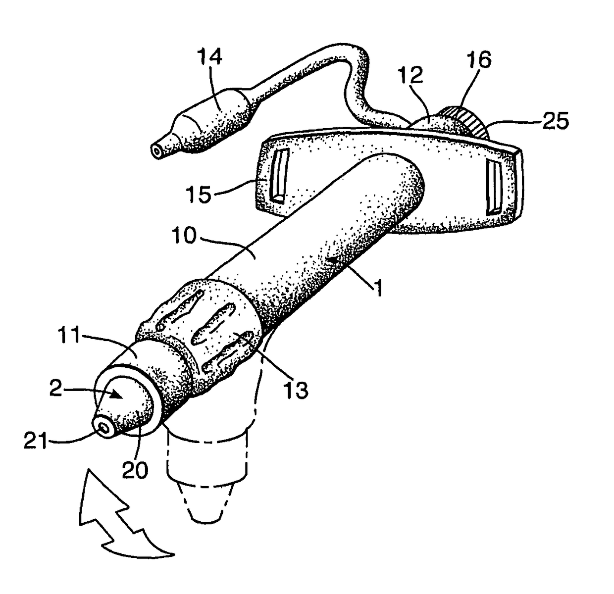
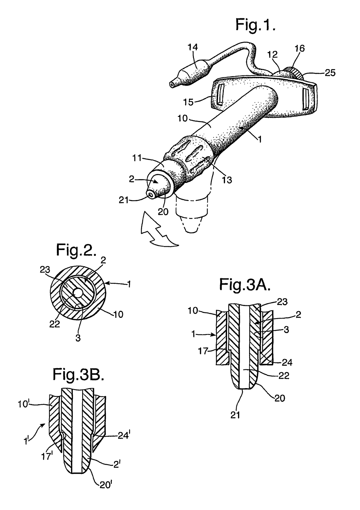
[0012]With reference first to FIGS. 1 to 3A, the assembly comprises an outer tube 1 and an introducer 2 extending along the bore 3 of the tube.

[0013]The tube 1 has a tubular shaft 10 of circular section and made of a soft, flexible plastics material. The flexibility of the shaft 10 is such that it cannot support its own weight when supported at one end so that, for example, its patient end 11 bends down under its own weight when the shaft is held at the machine end 12. The shaft 10 could be reinforced against radial forces by a helical wire or other reinforcement element within the wall of the shaft. The patient end 11 is square and rounded to provide a smooth tip to the tube. A sealing cuff 13 is attached to the outside of the shaft 10 in the usual way, just rearwardly of the patient end 11, the cuff being inflatable via an inflation line and connector 14. Towards its machine end 12, the tube has a flange 15 by which the tube can be secured in position about the patient's neck 4 us...


PUM


Abstract

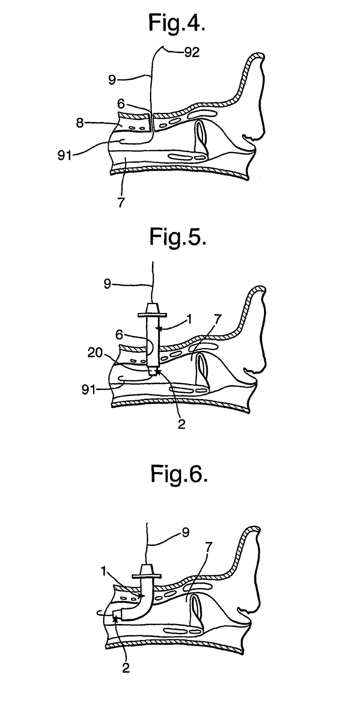
A tracheostomy tube assembly includes a flexible tube (1, 1′) and a flexible introducer (2, 2′) within the tube, the introducer having a passage (22) along its length for receiving a guidewire (9) inserted into the trachea (7) through a tracheostomy (6). The tube (1) has an inwardly-projecting collar (17, 17′) at its patient end (11), which engages an outwardly-projecting shoulder (24, 24′) on the introducer (2, 2′) so that the tube does not ride rearwardly along the introducer during insertion. The flexibility of the assembly is such that it can be inserted through the tracheostomy (6) while straight and then curves to follow the guidewire (9) as its patient end enters the trachea (7).

Description

BACKGROUND OF INVENTION[0001]This invention relates to tracheostomy tube assemblies of the kind including an outer, tubular shaft having a bore extending along it for passage of gas and an introducer inserted within the shaft, the assembly having a passage extending along its length for receiving an elongate guide member.[0002]Tracheostomy tubes have a curved or bent shaft shaped to extend through a surgically-made opening through the neck of a patient into the trachea. An introducer within the tube is used during insertion through the neck tissue to provide a tapered tip to the assembly. One end of the tube extends externally and usually has a flange used to secure the tube with the patient's neck. The other end of the tube locates within the trachea and is directed caudally. The tube often has a cuff adjacent the patient end, which can be inflated to seal with the trachea so that flow of gas is confined along the tube. It can be difficult to insert a conventional, curved tracheost...

Claims


Application Information

Patent Timeline
Patent Type & Authority Patents(United States)
IPC IPC(8): A61M16/04
CPCA61M16/0465A61M16/0472A61M16/0434A61M16/0488
Inventor BATEMAN, TIMOTHY
Owner SMITHS MEDICAL INT
Learn More