Eureka AIR delivers breakthrough ideas for toughest innovation challenges, trusted by R&D personnel around the world.

Multi-stage transmission for vehicle

a transmission and multi-stage technology, applied in mechanical equipment, transportation and packaging, gearing, etc., can solve the problems of reduced mountability and transfer efficiency, increased cost and weight of the transmission, etc., to improve the quietness of the vehicle, simple configuration, and operate more quietly

Active Publication Date: 2017-09-05
HYUNDAI MOTOR CO LTD
View PDF6 Cites 12 Cited by
  • Summary
  • Abstract
  • Description
  • Claims
  • Application Information

AI Technical Summary

Benefits of technology

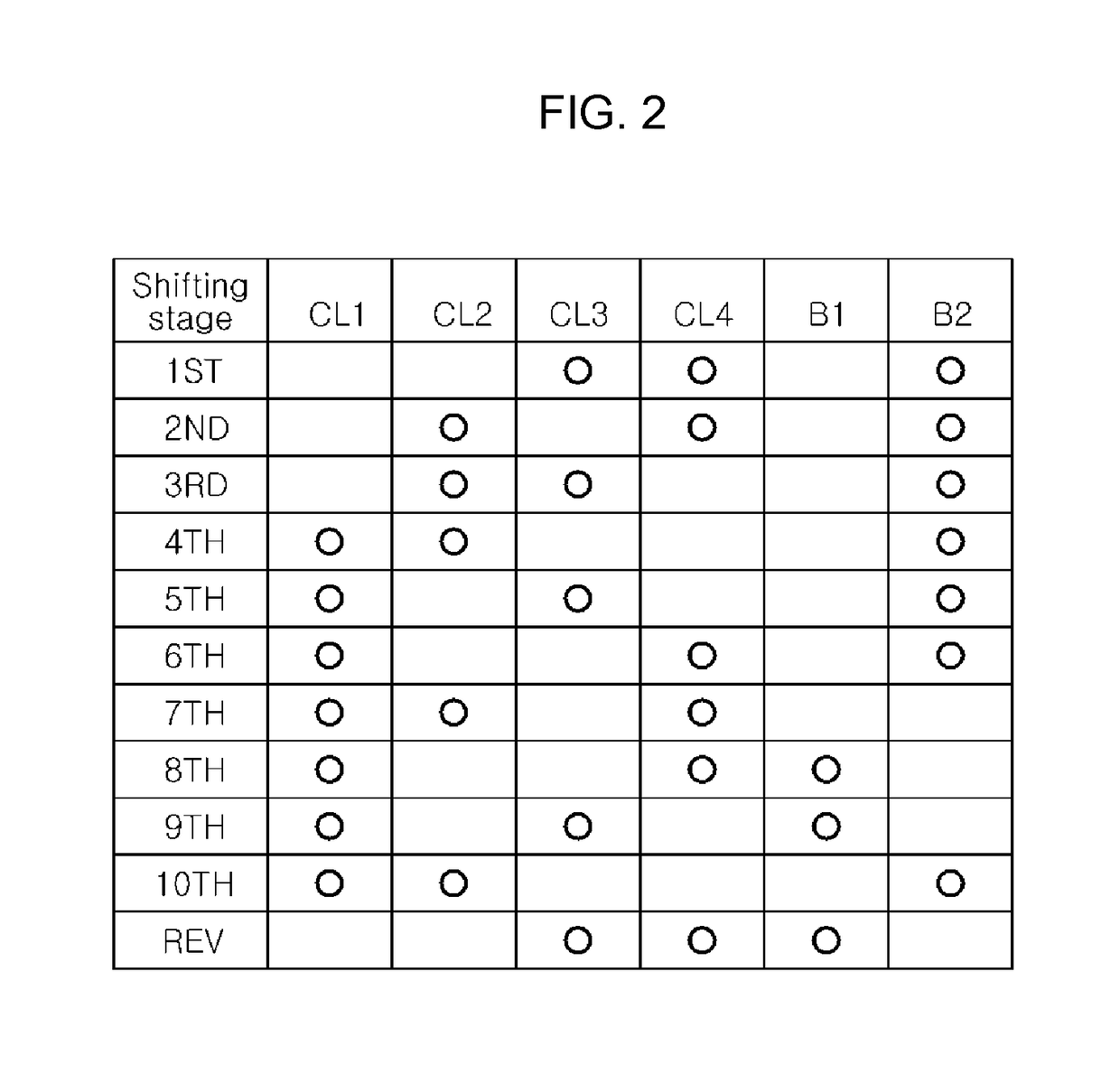
[0010]Various aspects of the present invention are directed to providing a multi-stage transmission for a vehicle that is able to realize at least ten forward shifting stages and one reverse shifting stage with a relatively small number of parts and a simple configuration such that an engine may be operated at optimum operation points, thereby maximizing an improvement in the fuel efficiency of the vehicle, and the engine may be operated more quietly, thereby improving the quietness of the vehicle.
[0018]According to the present invention as set forth above, the multi-stage transmission for a vehicle can realize at least ten forward shifting stages and one reverse shifting stage with a relatively small number of parts and a simple configuration such that the engine may be operated at optimum operation points, thereby maximizing an improvement in the fuel efficiency of the vehicle, and the engine may be operated more quietly, thereby improving the quietness of the vehicle.

Problems solved by technology

This may lead to undesirable effects instead, such as the reduced mountability and transfer efficiency and the increased cost and weight of the transmission.

Method used


Image

  • Multi-stage transmission for vehicle
  • Multi-stage transmission for vehicle
  • Multi-stage transmission for vehicle

Examples


Embodiment Construction

[0024]Reference will now be made in detail to various embodiments of the present invention(s), examples of which are illustrated in the accompanying drawings and described below. While the invention(s) will be described in conjunction with exemplary embodiments, it will be understood that the present description is not intended to limit the invention(s) to those exemplary embodiments. On the contrary, the invention(s) is / are intended to cover not only the exemplary embodiments, but also various alternatives, modifications, equivalents and other embodiments, which may be included within the spirit and scope of the invention as defined by the appended claims.

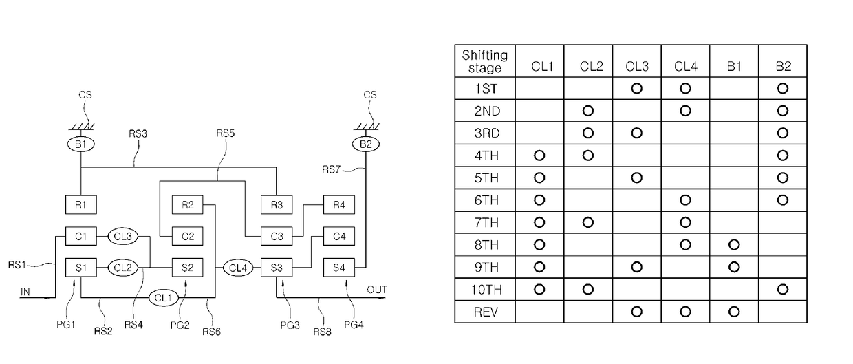
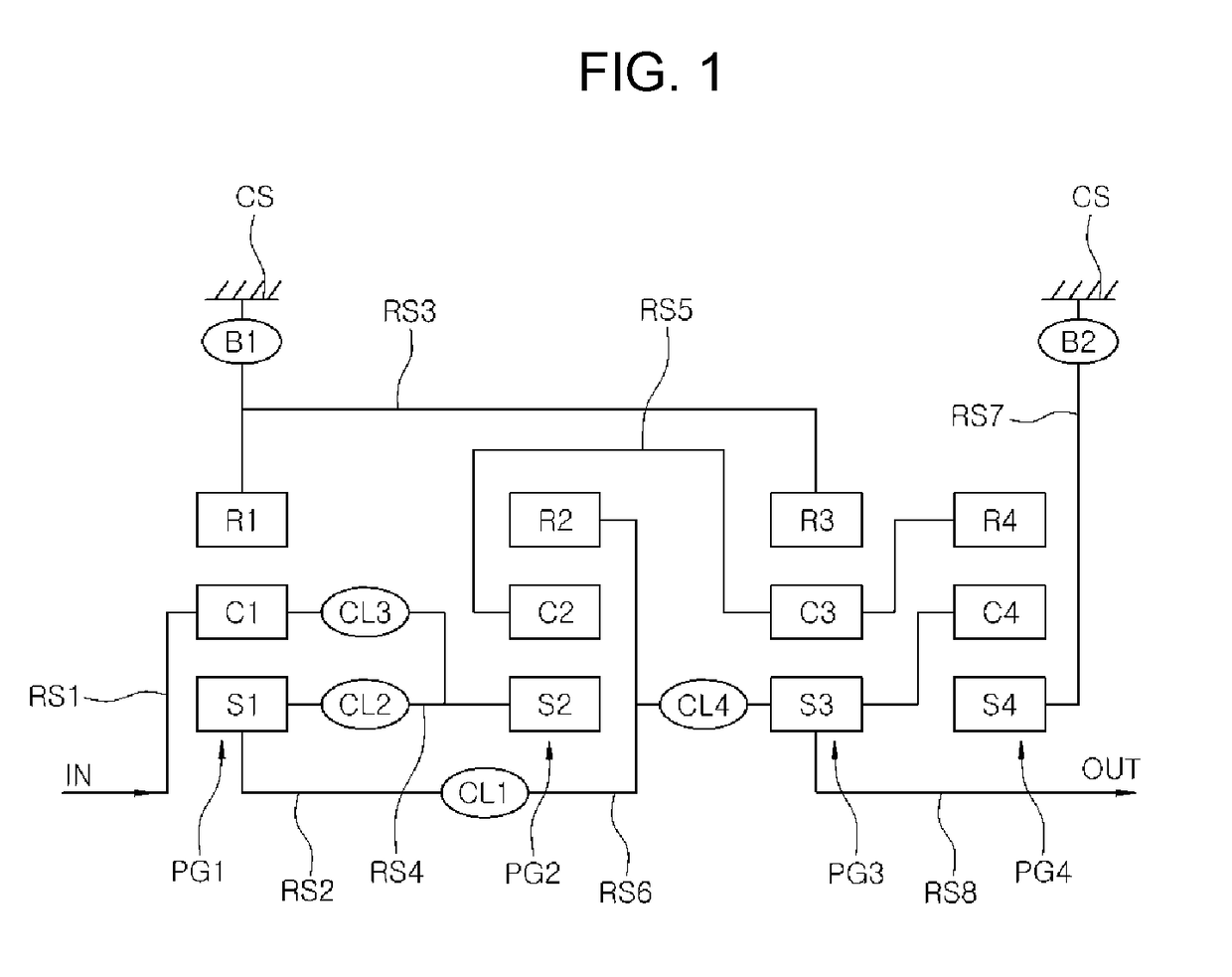
[0025]Referring to FIG. 1, a multi-stage transmission for a vehicle according to an exemplary embodiments of the present invention may include an input shaft IN, an output shaft OUT, a first to fourth planetary gear devices PG1, PG2, PG3 and PG4 disposed between the input shaft IN and the output shaft OUT to transmit rotary force,...


PUM


Abstract

A multi-stage transmission for a vehicle may include an input shaft; an output shaft; first to fourth planetary gear devices transmitting rotary force between the input and output shafts, each of them having three rotary elements, and at least six shifting elements connected to the rotary elements of the planetary gear devices; wherein a first rotary element of the first planetary gear device is variably connected to a first rotary element and a third rotary element of the second planetary gear device, a second rotary element is continuously connected to the input shaft and variably connected to the first rotary element of the second planetary gear device, and a third rotary element is installed to be fixable by any one of the shifting elements and continuously connected to a third rotary element of the third planetary gear device.

Description

CROSS-REFERENCE TO RELATED APPLICATION[0001]The present application claims priority to Korean Patent Application No. 10-2015-0080473, filed Jun. 8, 2015, the entire contents of which is incorporated herein for all purposes by this reference.BACKGROUND OF THE INVENTION[0002]Field of the Invention[0003]The present invention generally relates to a multi-stage transmission for a vehicle and, more particularly, to a multi-stage transmission technology able to realize as many shifting stages as possible using the few parts and the simple configuration as far as possible, thereby improving fuel efficiency of a vehicle.[0004]Description of Related Art[0005]Recent rising oil prices have driven worldwide car manufacturers into unlimited competition to improve fuel efficiency. In addition, great efforts have been made to reduce the weight and improve the fuel efficiency of engines based on a variety of techniques such as downsizing.[0006]Meanwhile, among methods that can be sought for transmis...

Claims


Application Information

Patent Timeline
Patent Type & Authority Patents(United States)
IPC IPC(8): F16H3/66
CPCF16H3/66F16H2200/0069F16H2200/2012F16H2200/2046F16H3/62
Inventor JI, SEONG WOOKKOOK, JAE CHANGHWANG, SEONG WOOKKWON, HYUN SIKCHO, WON MINSEO, KANG SOONOH, MYEONG HOON
Owner HYUNDAI MOTOR CO LTD
Why Eureka
Eureka Blog
Learn More