Control apparatus for hybrid vehicle

A technology for a hybrid vehicle and a control device, which is applied in the directions of a hybrid vehicle, a power device, a control device, etc., can solve the problem of not disclosing the driving force control, etc., and achieve the effects of improving quietness, simplifying the control system, and preventing tooth rattling noise.

Inactive Publication Date: 2009-01-14
TOYOTA JIDOSHA KK
View PDF3 Cites 13 Cited by
  • Summary
  • Abstract
  • Description
  • Claims
  • Application Information

AI Technical Summary

Problems solved by technology

[0013] Note that although the conventional techniques according to the above-mentioned Japanese Patent No. 3585121 and JP2005-232993A aim to suppress or prevent the occurrence of rattling noise by eliminating the looseness (corresponding to the gap) of the power distribution mechanism, there is no disclosure of the present invention. The technical idea of ​​coordinating the driving force control using the second electric motor and the braking force control using the vehicle brake disclosed in the application

Method used


Image

  • Control apparatus for hybrid vehicle
  • Control apparatus for hybrid vehicle
  • Control apparatus for hybrid vehicle

Examples


Embodiment Construction

[0043] The embodiments of the present invention will be described in detail below with reference to the drawings.

[0044] Figures 1 to 12 show embodiments of the present invention. In this embodiment, a front-engine rear-drive (FR) hybrid vehicle is taken as an example.

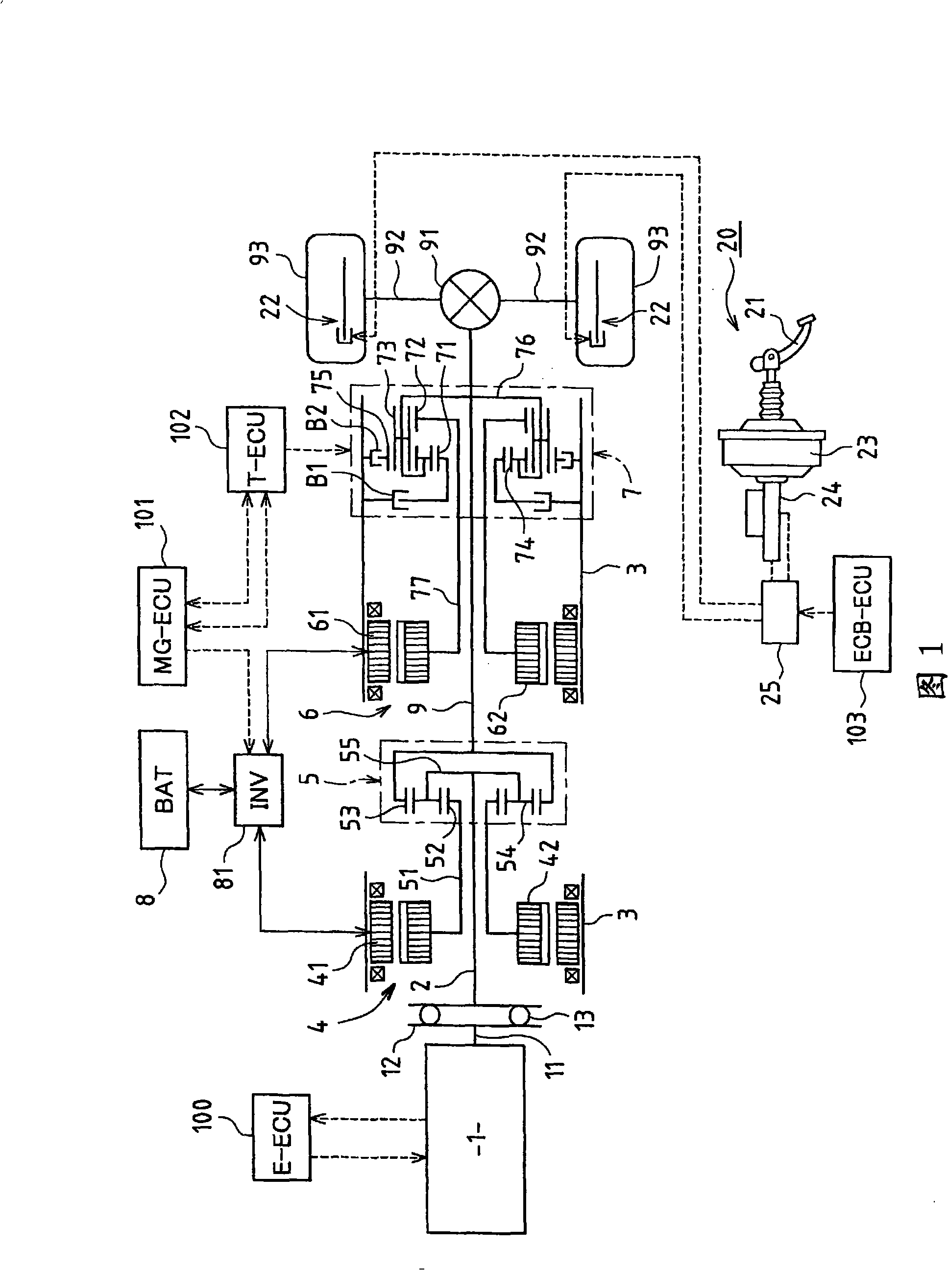
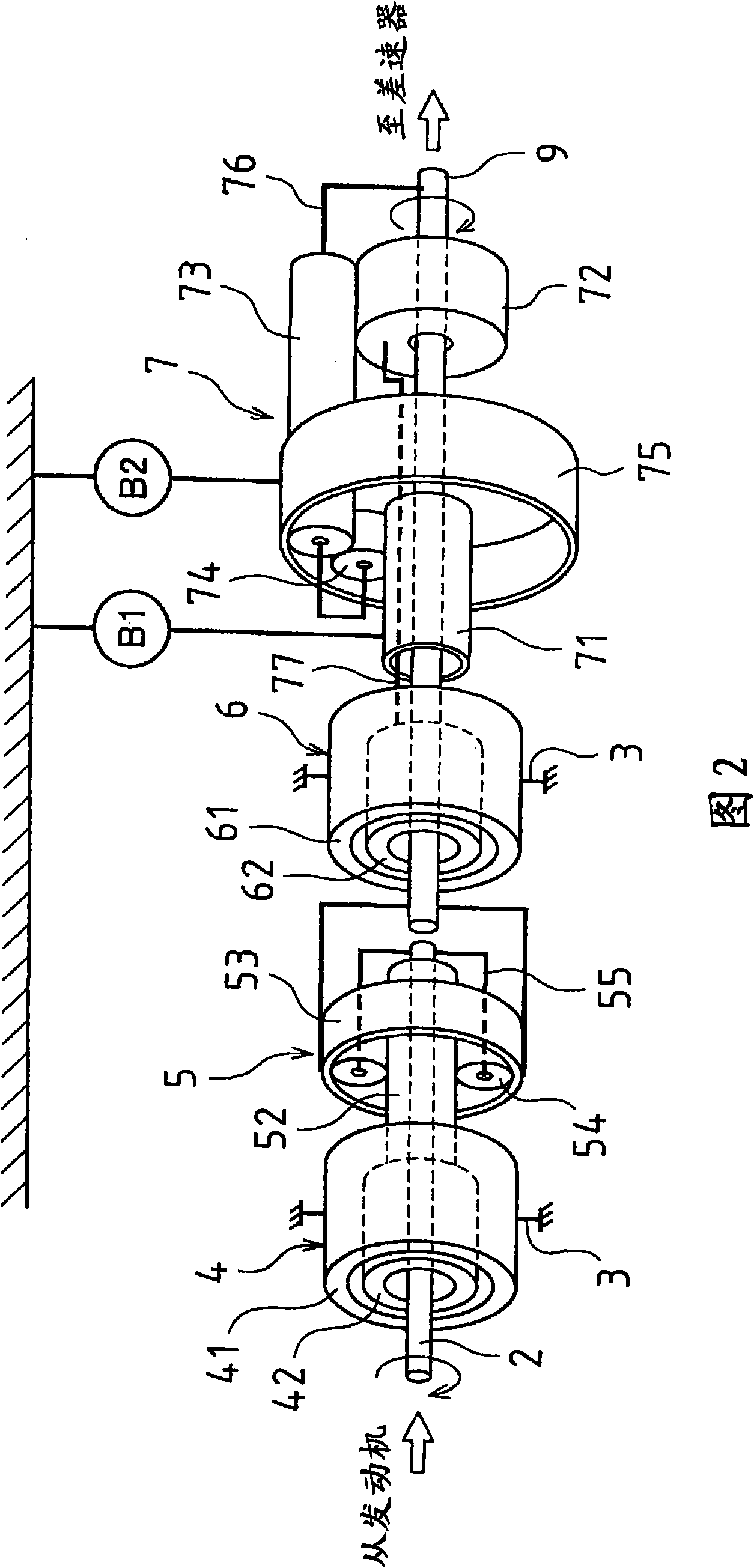
[0045] Hereinafter, before describing the part in which the features of the present invention are applied, an outline of a hybrid vehicle to which the present invention is applied will be described with reference to FIGS. FIG. 1 is a view showing a schematic structure of a hybrid vehicle, and FIG. 2 is a view showing a schematic view of a gear train of the hybrid vehicle.

[0046] The illustrated hybrid vehicle mainly includes an engine 1, a first motor generator 4 (MG1) that mainly functions as a generator, a power distribution mechanism 5, a second motor generator 6 (MG2) that mainly functions as a motor, and a reduction mechanism 7 .

[0047] The first motor generator 4, the power distribution mechanism 5, th...


PUM


Abstract

In one embodiment, a first motor is used upon stopping or starting of an engine during driving of a vehicle. When a stop control or a start control of the engine is executed, a target drive force required to be generated by a second motor is calculated based on a drive force required for driving. A positive drive force required for elimination in a specific rotation direction of backlash occurring in mutual meshing sections of gears of a power distribution mechanism is added to the target drive force. Meanwhile, a braking force required of a brake in order to cancel the added positive drive force so as not to be transmitted to drive wheels is calculated. Based on the results of calculation, coordinated control is executed in which the second motor and the brake are operated in a linked manner.

Description

[0001] This application claims priority from Japanese Patent Application No. 2007-180080 filed in Japan on July 9, 2007, and the entire content of the application is incorporated herein by reference. Technical field [0002] The present invention relates to a control device used in a hybrid vehicle having an engine and an electric motor (motor) as drive sources. The hybrid vehicle is equipped with a planetary gear type power distribution mechanism in order to output the driving force generated by the engine, the electric motor, or both to the driving wheels. Background technique [0003] In terms of conventional technology, hybrid vehicles equipped with, for example, two motor generators have been proposed, each of which can be selectively used as a motor or as a generator (for example, see JP2005-212494A, Japan Patent No. 3585121 and JP2005-232993A). [0004] In a hybrid vehicle, a first motor generator, a power split mechanism, a second motor generator, and a speed reduction mec...

Claims


Application Information

Patent Timeline
Patent Type & Authority Applications(China)
IPC IPC(8): B60W20/00B60W40/10B60K6/365B60K6/445B60L50/16B60W10/06B60W10/18F02D29/02F02N11/04
CPCB60L2240/423Y02T10/6239Y02T10/6286F16H2200/2023B60W2540/12B60W2520/10F16H2200/2035B60W10/06B60K6/365B60K6/547F16H2037/0873B60W2710/083B60K6/445F16H2037/103B60W20/00F16H2200/2007F16H3/728B60W2510/0604B60K1/02Y02T10/642B60W2510/0638B60W10/08B60L2240/441Y02T10/62Y02T10/64B60K2006/268B60W20/15B60W20/10B60W10/115
Inventor 金山武司
Owner TOYOTA JIDOSHA KK
Why Eureka
Try Eureka