
Vehicle brake control device

Inactive Publication Date: 2015-10-01
TOYOTA JIDOSHA KK
View PDF13 Cites 11 Cited by
  • Summary
  • Abstract
  • Description
  • Claims
  • Application Information

AI Technical Summary

Benefits of technology

The present invention aims to enhance the quietness of hydraulic control in a wheel cylinder. The invention provides a solution to remove contaminants that can obstruct the pressure-increasing linear control valve used for adjusting the hydraulic pressures of wheel cylinders. A contaminant removal control unit opens the valve for a short period to remove any contaminants that may get stuck inside it. This prevents the valve from becoming ineffective due to contamination, and also avoids the need for frequent maintenance. Additionally, the invention also prevents a situation where the on-off valve of the master cut valve device is repeatedly opened and closed, which can cause unfavorable hydraulic pressure situations.

Problems solved by technology

However, such brake control device has a problem of an operating noise of the linear control valve that provides uncomfortable feeling to a driver.
This operating noise is generated due to a hydraulic pulsation that occurs at the moment the linear control valve is opened.
These linear control valves are individually activated, resulting in that much operating noise is generated, and a countermeasure against the operating noise is demanded.

Method used


Image

  • Vehicle brake control device
  • Vehicle brake control device
  • Vehicle brake control device

Examples


first embodiment

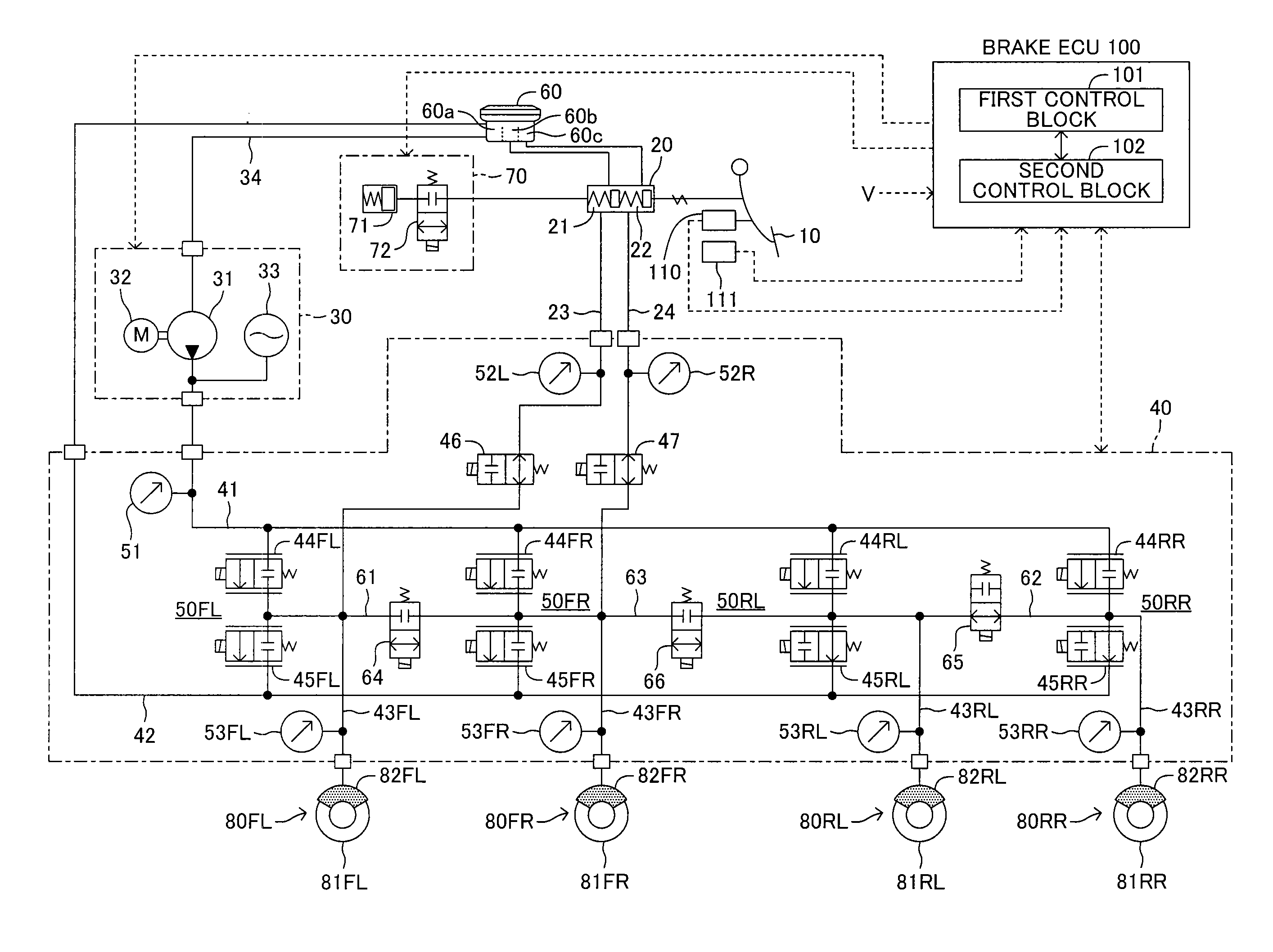
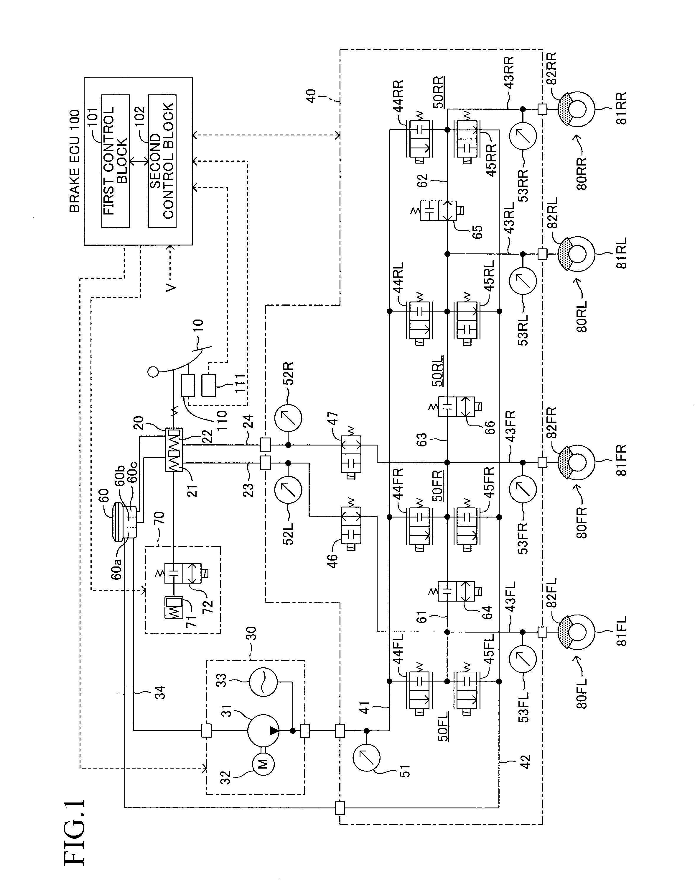
[0177]FIG. 17 is a flowchart illustrating the remaining hydraulic pressure prevention control in step S40. After starting the remaining hydraulic pressure prevention routine, the brake ECU 100 reads the wheel cylinder pressures PwFL and PwFR for the front wheels detected by the hydraulic pressure sensors 53FL and 53FR in step S401. Then, the brake ECU 100 determines in step S402 whether a remaining hydraulic pressure occurs or not based on the wheel cylinder pressures PwFL and PwFR. For example, the brake ECU 100 compares the wheel cylinder pressures PwFL and PwFR and a remaining hydraulic pressure determination threshold values Pwref. When at least one of the wheel cylinder pressures PwFL and PwFR is larger than the remaining hydraulic pressure determination threshold values Pwref, the brake ECU 100 determines that the remaining hydraulic pressure occurs. When determining that the remaining hydraulic pressure does not occur (S402: No), the brake ECU 100 closes the pressure-decreasi...

third embodiment

[0186]FIG. 19 is a flowchart illustrating the third embodiment involved with the remaining hydraulic pressure prevention process in step S40. The processes same as those in the remaining hydraulic pressure prevention routine in FIG. 17 are identified by the same reference numerals, and these processes will merely briefly be described. After the remaining hydraulic pressure prevention routine is started, the brake ECU 100 reads the wheel cylinder pressures PwFL and PwFR for the front wheels in step S401. Then, the brake ECU 100 determines in step S402 whether a remaining hydraulic pressure occurs or not based on the wheel cylinder pressures PwFL and PwFR. When determining that the remaining hydraulic pressure does not occur (S402: No), the brake ECU 100 determines in step S421 whether the master cut valves 46 and 47 are now opened or not. Just after the remaining hydraulic pressure prevention routine is started, the master cut valves 46 and 47 are closed. Therefore, the brake ECU 100...

fourth embodiment

[0194]FIG. 20 is a flowchart illustrating the fourth embodiment involved with the remaining hydraulic pressure prevention process in step S40. The processes same as those in the remaining hydraulic pressure prevention routine in FIG. 19 are identified by the same reference numerals, and these processes will merely briefly be described. After the remaining hydraulic pressure prevention routine is started, the brake ECU 100 reads the wheel cylinder pressures PwFL and PwFR for the front wheels in step S401. Then, the brake ECU 100 determines in step S402 whether a remaining hydraulic pressure occurs or not based on the wheel cylinder pressures PwFL and PwFR. When determining that the remaining hydraulic pressure does not occur (S402: No), the brake ECU 100 keeps the master cut valves 46 and 47 closed.

[0195]On the other hand, when determining that the remaining hydraulic pressure occurs on at least one of the wheel cylinders 82FL and 82FR (S402: Yes), the brake ECU 100 opens the master ...


PUM


Abstract

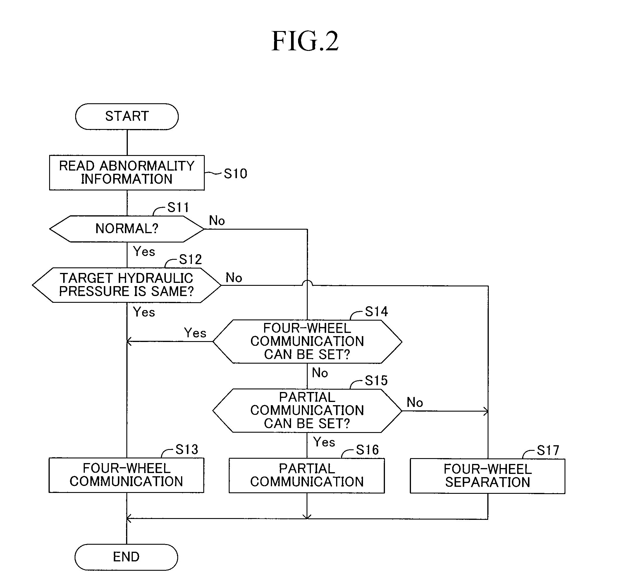
A brake control device includes a front-wheel left-right communication passage that allows communication between wheel cylinders for a front-left wheel and a front-right wheel via a front-wheel communication on-off valve; a rear-wheel left-right communication passage that allows communication between wheel cylinders for a rear-left wheel and a rear-right wheel via a rear-wheel communication on-off valve; and a front-rear communication passage that allows communication between a wheel cylinder of either one of the front-left and front-right wheels and a wheel cylinder of either one of the rear-left and rear-right wheels via a front-rear communication on-off valve, wherein the brake control device keeps the front-wheel communication on-off valve, the rear-wheel communication on-off valve, and the front-rear communication on-off valve opened to set a mode to a four-wheel communication mode during a normal brake control. With this, some of linear control valves are deactivated, whereby an operating noise can be reduced.

Description

TECHNICAL FIELD[0001]The present invention relates to a vehicle brake control device that can independently control a hydraulic pressure of each of front-left, front-right, rear-left, and rear-right wheels by using a linear control valve.BACKGROUND ART[0002]Conventionally, as proposed in Patent Document 1, there has been known a vehicle brake control device including linear control valves (composed of a pressure-increasing linear control valve and a pressure-decreasing linear control valve), each of which is provided on an individual passage for operating fluid from a power hydraulic pressure generating device to each wheel cylinder, the brake control device independently controlling a hydraulic pressure of a wheel cylinder for each wheel according to an energization control of the linear control valves. In the brake control device controlling the hydraulic pressure of the wheel cylinder for each wheel, a target hydraulic pressure according to a driver's brake operation is set, the ...

Claims


Application Information

Patent Timeline
IPC IPC(8): B60T13/68B60T8/34B60T8/171
CPCB60T13/686B60T8/348B60T8/171B60T8/3655B60T8/4081B60T7/042B60T13/143B60T13/146B60T13/662
Inventor MIYAZAKI, TETSUYANIMURA, KAZUNORI
Owner TOYOTA JIDOSHA KK
Learn More