
Transport refrigeration system with engine shaft horsepower augmentation

a refrigeration system and onboard engine technology, applied in the field of shaft horsepower output augmentation of onboard engines, can solve the problems of increased fuel consumption, low idle speed of diesel engines, and low efficiency of diesel engines, and achieve the effect of reducing shaft horsepower demand

Active Publication Date: 2017-09-12
CARRIER CORP
View PDF20 Cites 23 Cited by
  • Summary
  • Abstract
  • Description
  • Claims
  • Application Information

AI Technical Summary

Benefits of technology

The patent aims to decrease the engine's demand for shaft horsepower when the transport refrigeration unit is running under maximum refrigeration hold conditions. The technical effect of this invention is to reduce the strain on the engine and improve the efficiency of the transport refrigeration unit.

Problems solved by technology

During standstill, the diesel engine is typically idling at low speed.
Therefore, during the temperature maintenance mode and standstill mode, the diesel engine is operating at lower efficiency and with increased fuel consumption.

Method used


Image

  • Transport refrigeration system with engine shaft horsepower augmentation
  • Transport refrigeration system with engine shaft horsepower augmentation
  • Transport refrigeration system with engine shaft horsepower augmentation

Examples


Embodiment Construction

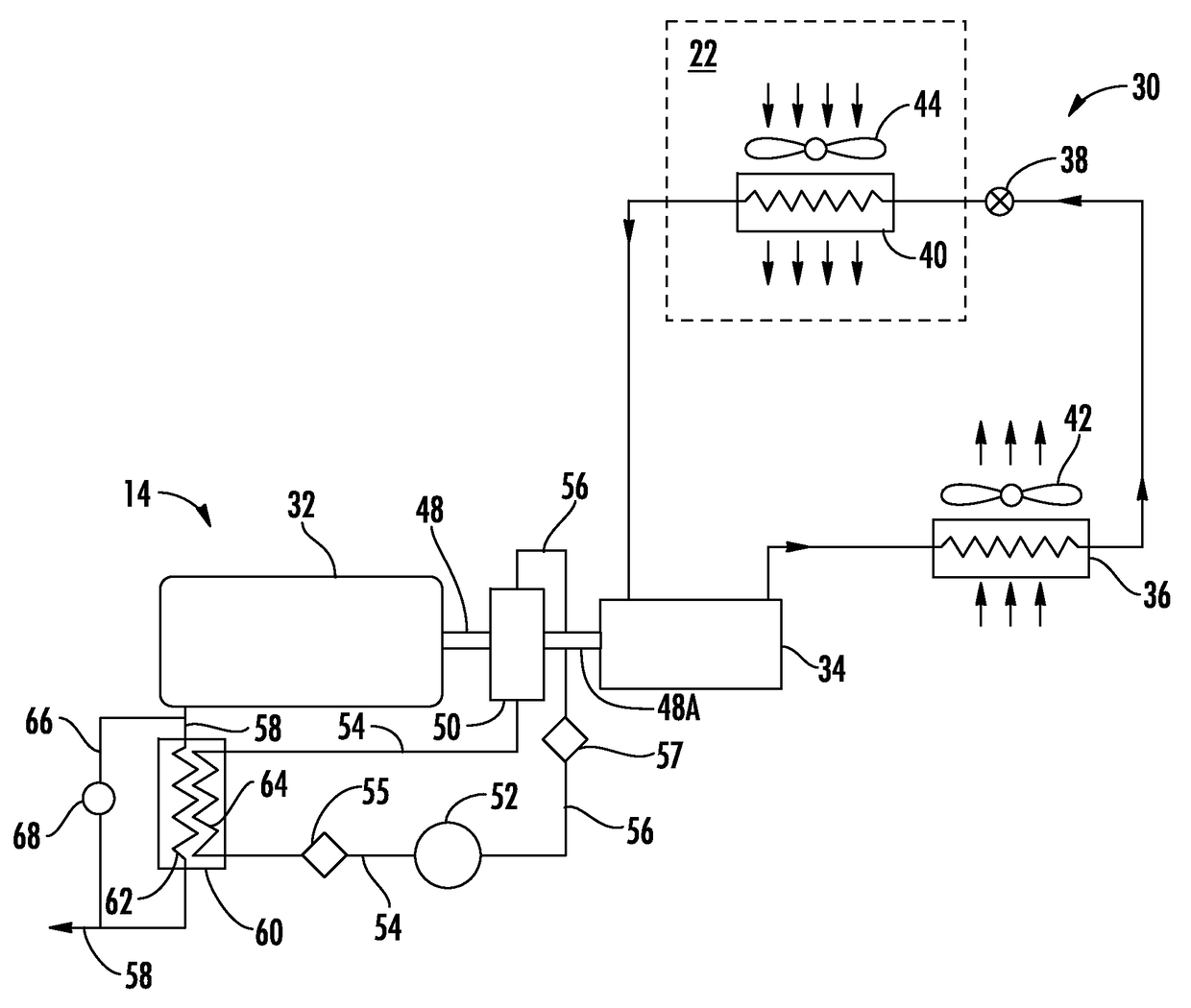
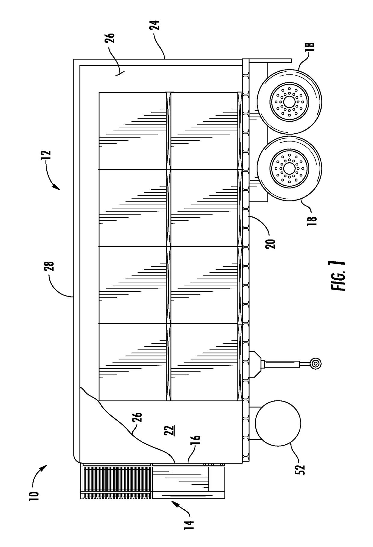
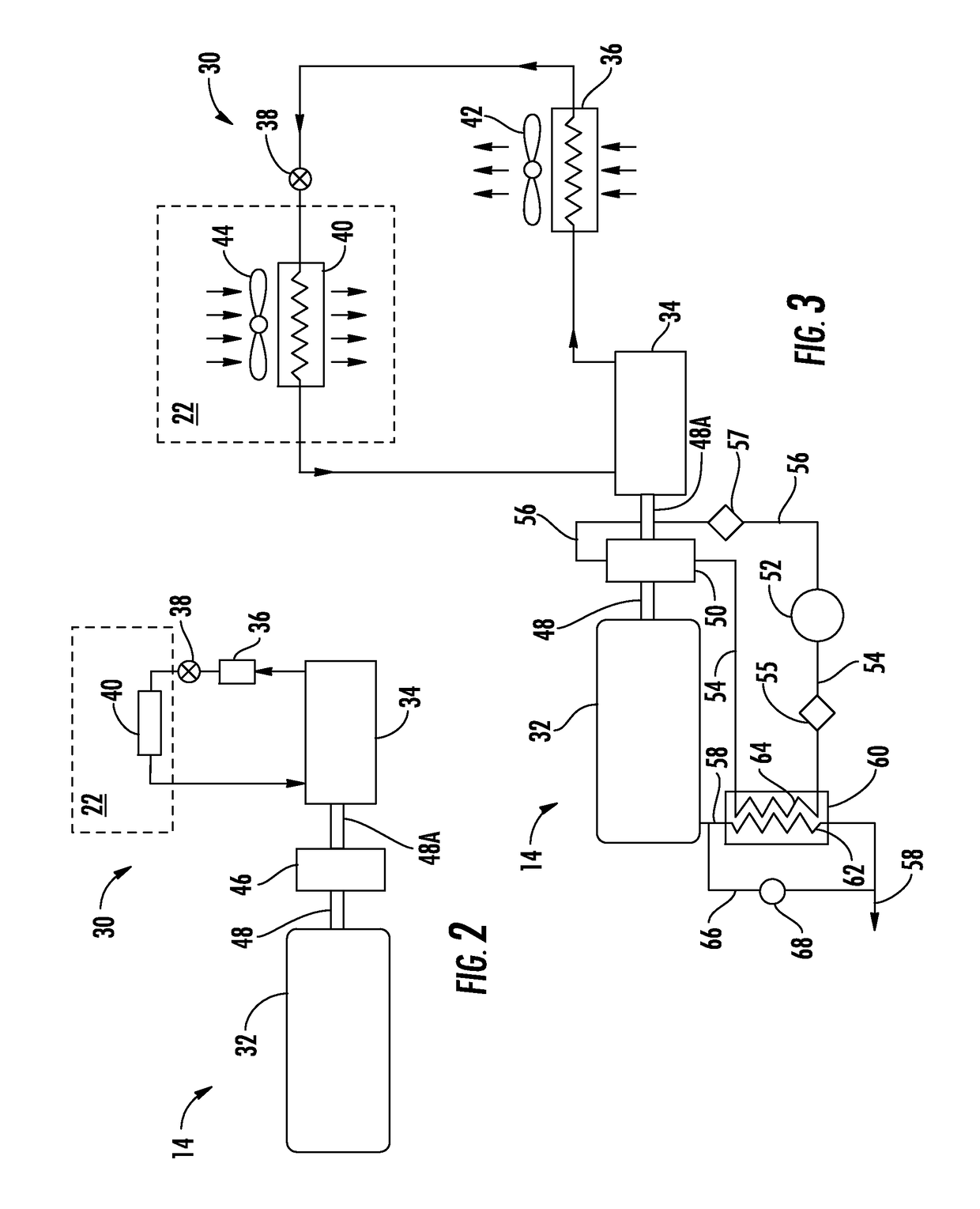
[0024]Referring initially to FIG. 1, there is illustrated a mobile refrigerated unit, generally referenced 10, depicted as a refrigerated trailer 12, equipped with a transport refrigeration system 14 mounted as in conventional practice to a front wall 16 of the trailer 12. The trailer 12 is equipped with wheels 18 mounted beneath the trailer bed 20 so that the trailer can be drawn by a cab or tractor from place to place. A refrigerated cargo space 22 is defined within a cargo box defined by the front wall 16, a rear wall 24, a pair of side walls 26, the trailer bed 20 and a ceiling 28, all being of standard construction in the industry. A set of doors (not shown), typically mounted in the rear wall 24 of the cargo box, provided access to the refrigerated cargo space 22. The cargo box may be provided with appropriate seals, as in conventional practice, to prevent, or at least minimize, air from inside the refrigerated cargo space 22 escaping to the atmosphere outside the trailer 12 w...


PUM


Abstract

Shaft horsepower output associated with a prime mover for driving a component of a transport refrigeration system may be selectively augmented through an auxiliary power apparatus. In an embodiment, a compressed air engine is provided and selectively operable to augment the shaft horsepower output for driving the component. At least one storage tank is provided for storing compressor air and at least one air compressor is provided for generating and supplying compressed air to the at least one compressed air storage tank. In an embodiment, the prime mover is a fuel combustion engine and the compressed air is heated by exhaust gas from the fuel combustion engine. The driven component may be a refrigerant compressor. The driven component may be an electric generator.

Description

CROSS-REFERENCE TO RELATED APPLICATION[0001]Reference is made to and this application claims priority from and the benefit of U.S. Provisional Application Ser. No. 61 / 577,739, filed Dec. 20, 2011, and entitled TRANSPORT REFRIGERATION SYSTEM WITH ENGINE SHAFT HORSEPOWER AUGMENTATION, which application is incorporated herein in its entirety by reference.BACKGROUND OF THE INVENTION[0002]This invention relates generally to transport refrigeration systems for refrigerating perishable cargo in the cargo space of a trailer or other mobile refrigerated container and, more particularly, to shaft horsepower output augmentation of an onboard engine for powering a refrigerant compressor of a transport refrigeration unit.[0003]Refrigerated trucks and trailers are commonly used to transport perishable cargo, such as, for example, produce, meat, poultry, fish, dairy products, cut flowers, and other fresh or frozen perishable products stowed in a temperature-controlled space, commonly referred to a...

Claims


Application Information

Patent Timeline
Patent Type & Authority Patents(United States)
IPC IPC(8): B60P3/20B60H1/32B60H1/00F25D11/00
CPCB60H1/00428B60H1/00435B60H1/3232B60P3/20F25D11/003
Inventor STEELE, JOHN T.
Owner CARRIER CORP
Learn More