Movement joint

a technology of moving joints and joints, applied in the direction of bridges, roads, constructions, etc., can solve the problems of insufficient level of the sub-base on which the concrete is laid, cost and complexity in fabrication, and eventual deterioration of the joints, so as to improve the free movement

Active Publication Date: 2017-09-19
PERMABAN LTD
View PDF23 Cites 9 Cited by
  • Summary
  • Abstract
  • Description
  • Claims
  • Application Information

AI Technical Summary

Benefits of technology

[0015]The object of the present invention is to pro

Problems solved by technology

It may not be the full depth of the slabs in that the sub-base on which the concrete is laid may not be sufficiently level for the divider to abut the sub-base along the entire length of the joint.
Despite providing a good measure of protection against spalling, this joint has an inherent problem in that, wherever a joint is straight and has op

Method used


Image

  • Movement joint
  • Movement joint
  • Movement joint

Examples


Embodiment Construction

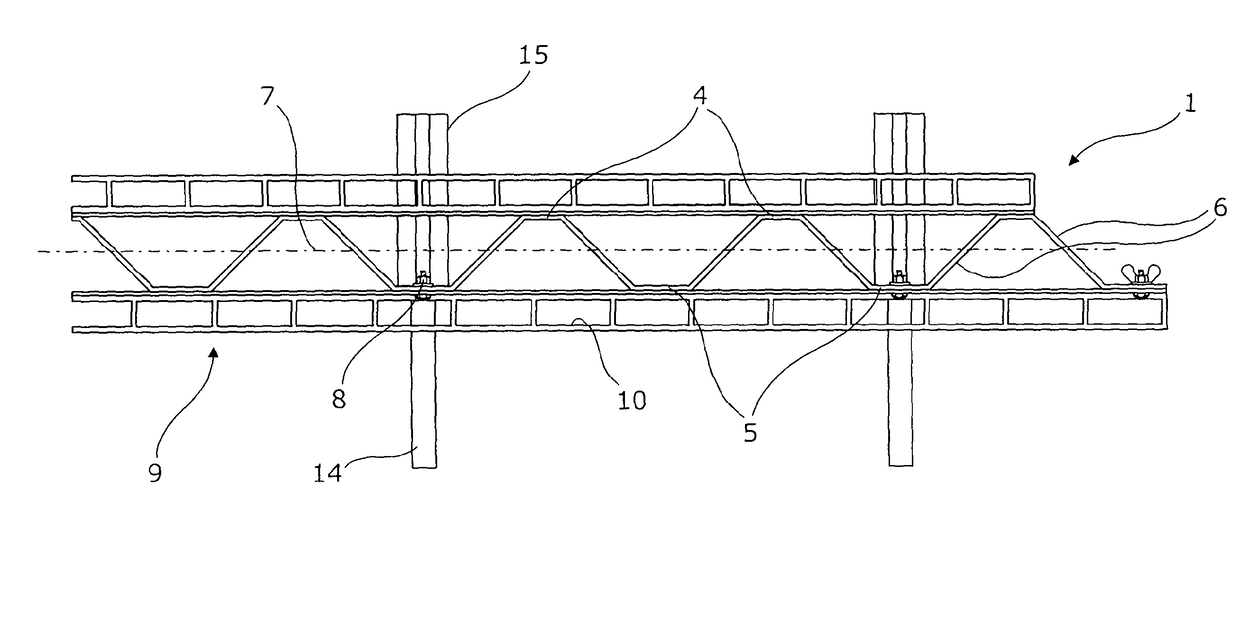
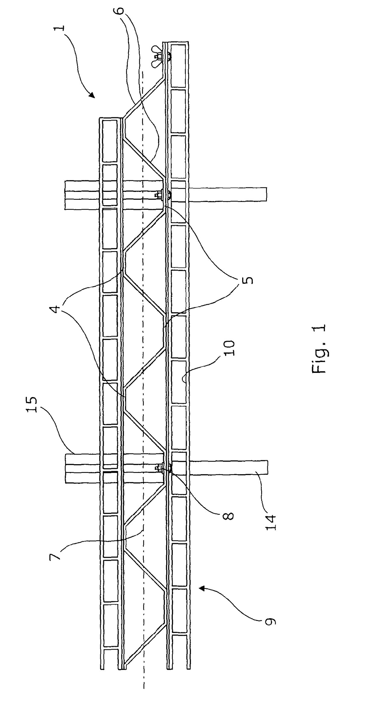
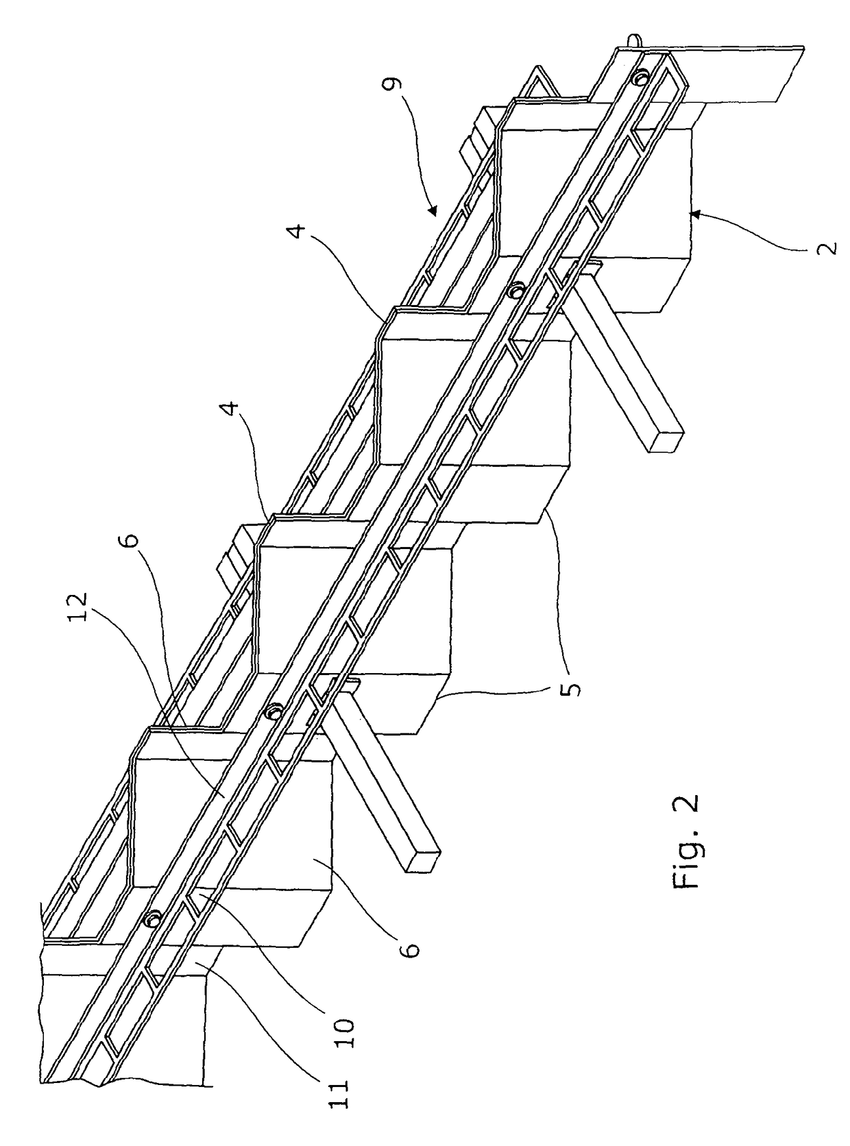
[0048]Referring to the drawings, a free movement, arris protection, construction joint 1 has a pair of arris protection members 2,3 formed complementarily from strips of sheet with a continuous trapezium wave form. A divider one 2 of the members is typically 100 mm deep for a nominal 0.1 m deep slab. The other one 3 is typically 50 mm deep. The members are of 2 mm steel plate, either mild (possibly galvanised) or stainless.

[0049]The wave form is comprised of flanges 4,5, typically extending 150 mm in the length of the joint and of webs 6, extending at 45° to the flanges and the length of the joint. The flanges 4,5 are spaced 150 mm on opposite sides of a mid-plane 7 of the joint. The members 2,3 are bolted together with flangible nylon bolts 8, with their top (in use) edges flush.

[0050]Welded to the outer ones of the flanges are L strips 9 having apertures 10 in their flats 11 extending from the flanges for anchoring the joint to its slabs. The bolts pass through welded on ones 12 o...


PUM


Abstract

A free movement, arris protection, construction joint has a pair of arris protection members formed complementarily from strips of sheet with a continuous trapezium wave form. A divider one of the members is typically 100 mm deep for a nominal 0.1 m deep slab. The other one is typically 50 mm deep. The members are of steel plate.
The wave form is comprised of flanges extending in the length of the joint and of webs angled to the flanges and the length of the joint. The flanges are spaced on opposite sides of a mid-plane of the joint. The members are bolted together with flangible nylon bolts, with their top (in use) edges flush. Welded to the outer ones of the flanges are L strips having apertures in their flats extending from the flanges for anchoring the joint to its slabs.

Description

CROSS REFERENCE TO RELATED APPLICATION[0001]This application is for entry into the U.S. National Phase under §371 for International Application No. PCT / GB2012 / 000694 having an international filing date of Aug. 31, 2012, and from which priority is claimed under all applicable sections of Title of the United States Code including, but not limited to, Sections 120, 363, and 365(c), and which in turn claims priority under 35 USC 119 to United Kingdom Patent Application No. 1115940.7 filed on Sep. 14, 2011.BACKGROUND OF THE INVENTION[0002]Field of the Invention[0003]The present invention relates to a movement joint, in particular of the type used in the laying of concrete, remaining in place thereafter and allowing free movement of concrete slabs on opposite sides of the joint.[0004]Description of the Related Art[0005]Movement joints are provided between concrete slabs to allow them to separate at intended joint lines as the concrete shrinks on curing after laying.[0006]Many joints inclu...

Claims


Application Information

Patent Timeline
IPC IPC(8): E01C11/02E01D19/06E01C11/08E01C11/04E01C11/06E01C11/14
CPCE01C11/08E01C11/04E01C11/06E01C11/14E01D19/06E01D19/062
Inventor KEEN, ANDREW
Owner PERMABAN LTD
Why Eureka
Try Eureka